When a capacity safety factor is used, the compressor is selected at its maximum speed to handle design load plus safe- ty factor. Multiplying factors for
Whether or not added capacity offered by the safety factor is incorporated at once is a matter of judgment. If it is, then the compressor will be operated at maximum speed at the start and any excess capacity achieved will be reflected in faster
pulldowns or lower temperatures. It is also a good practice to drive the machine at a speed that will provide slightly more rated capacity than is required by design load. Additional
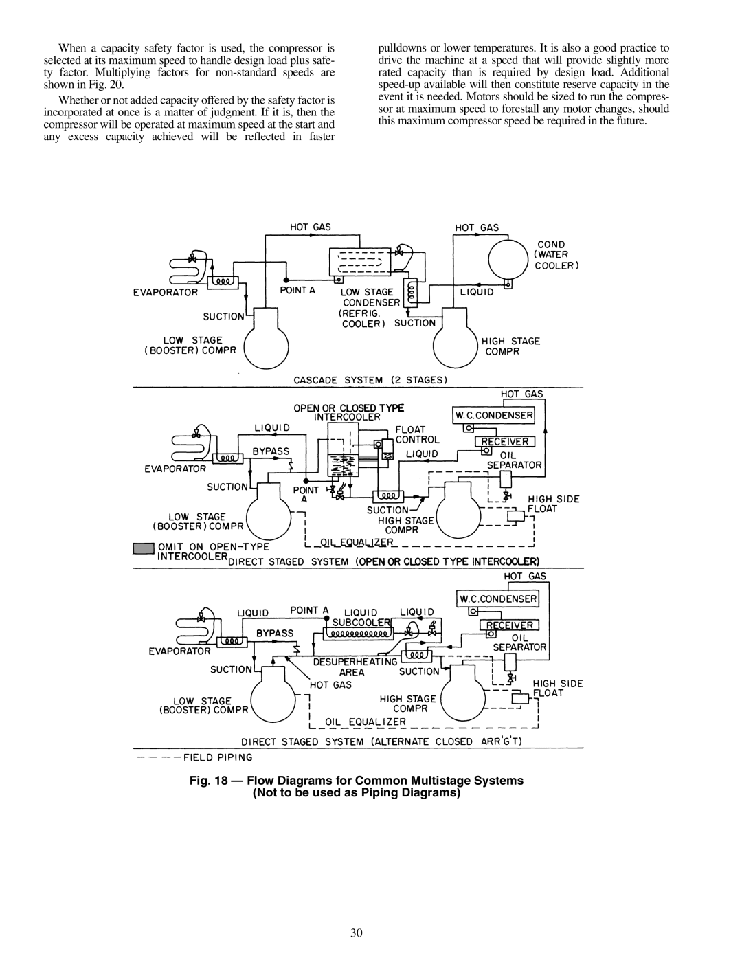
Fig. 18 — Flow Diagrams for Common Multistage Systems
(Not to be used as Piping Diagrams)
30