|
|
| Table 23 — Booster “R” Factors |
|
| ||||||
| SUCT |
|
|
| DISCHARGE TEMPERATURE (F) |
|
| ||||
| TEMP |
| 0 | 10 | 20 | 30 | |||||
| (F) |
|
|
|
|
|
|
|
|
| |
|
|
|
|
|
|
|
|
|
|
| |
|
| — | 1.230 | 1.276 | 1.328 | 1.377 | 1.429 | 1.470 | — | — | |
|
| — | 1.186 | 1.230 | 1.280 | 1.330 | 1.380 | 1.421 | 1.458 | 1.489 | |
|
| — | — | 1.183 | 1.233 | 1.284 | 1.334 | 1.375 | 1.410 | 1.441 | |
|
| — | — | — | 1.189 | 1.238 | 1.287 | 1.328 | 1.363 | 1.397 | |
|
| — | — | — | — | 1.190 | 1.240 | 1.280 | 1.318 | 1.350 | |
|
| — | — | — | — | — | 1.291 | 1.234 | 1.270 | 1.307 | |
|
|
|
|
|
|
|
|
|
|
| |
| 1.261 | 1.310 | 1.360 | 1.410 | 1.453 | — | — | — | — | ||
| 1.221 | 1.271 | 1.319 | 1.371 | 1.414 | — | — | — | — | ||
|
| ||||||||||
| 1.214 | 1.263 | 1.313 | 1.361 | 1.407 | 1.448 | — | — | — | ||
| 1.175 | 1.221 | 1.270 | 1.321 | 1.368 | 1.408 | — | — | — | ||
|
| ||||||||||
| 1.170 | 1.218 | 1.269 | 1.315 | 1.360 | 1.400 | 1.434 | — | — | ||
| 1.129 | 1.172 | 1.221 | 1.271 | 1.319 | 1.359 | 1.394 | — | — | ||
|
| ||||||||||
|
| — | 1.172 | 1.221 | 1.269 | 1.313 | 1.351 | 1.388 | 1.424 | — | |
|
| — | 1.125 | 1.173 | 1.221 | 1.270 | 1.311 | 1.348 | 1.382 | — | |
|
|
| |||||||||
|
| — | — | 1.178 | 1.220 | 1.267 | 1.303 | 1.340 | 1.377 | 1.406 | |
|
| — | — | 1.125 | 1.172 | 1.221 | 1.263 | 1.300 | 1.337 | 1.367 | |
|
|
| |||||||||
|
| — | — | — | 1.175 | 1.219 | 1.256 | 1.291 | 1.329 | 1.360 | |
|
| — | — | — | 1.123 | 1.173 | 1.217 | 1.252 | 1.289 | 1.319 | |
|
|
| |||||||||
|
| — | — | — | — | 1.171 | 1.209 | 1.245 | 1.281 | 1.311 | |
|
| — | — | — | — | 1.126 | 1.169 | 1.205 | 1.241 | 1.261 | |
|
|
| |||||||||
|
| — | — | — | — | — | 1.160 | 1.199 | 1.233 | 1.265 | |
|
| — | — | — | — | — | 1.121 | 1.159 | 1.196 | 1.227 | |
|
|
| |||||||||
|
|
| |||||||||
|
|
|
|
|
| [0.212 x low stage bhp] |
|
| |||
NOTE: For |
|
| |||||||||
| 50 |
|
|
|
|
|
|
|
|
|
|
| 40 |
|
|
|
|
|
|
|
|
|
|
| 30 |
|
|
|
|
|
|
|
|
|
|
| 20 |
|
|
|
|
|
|
|
|
|
|
| 15 |
|
|
|
|
|
|
|
|
|
|
| 10 |
|
|
|
|
|
|
|
|
|
|
OF REFRIGERATION | 9 |
|
|
|
|
|
|
|
|
|
|
8 |
|
|
|
|
|
|
|
|
|
| |
7 |
|
|
|
|
|
|
|
|
|
| |
6 |
|
|
|
|
|
|
|
|
|
| |
5 |
|
|
| SATURATED |
|
|
|
|
| ||
4 |
|
|
|
|
|
|
|
| |||
3 |
|
|
|
| SUCTION |
|
|
|
| ||
TONS |
|
|
|
|
|
|
|
| |||
|
|
|
|
|
|
|
|
| |||
|
|
|
|
|
| TEMPERATURE |
|
| |||
| 2 |
|
|
|
|
|
|
| |||
|
|
|
|
|
|
|
|
| |||
|
|
|
|
|
|
|
|
| F |
|
|
|
|
|
|
|
|
|
|
| - |
|
|
|
|
|
|
|
|
|
|
| 100 |
|
|
| 1 |
|
|
|
|
|
| - |
|
|
|
|
|
|
|
|
|
| 90 |
|
|
| |
|
|
|
|
|
| - |
|
|
|
| |
|
|
|
|
|
|
| 80 |
|
|
|
|
|
|
|
|
|
| - |
|
|
|
|
|
|
|
|
|
|
| 60 |
|
|
|
|
|
|
|
|
| - |
|
|
|
|
|
|
|
|
|
|
| 40 |
|
|
|
|
|
| |
| 0.5 | 10 | 15 | 20 | 30 | 40 | 50 | 60 |
| 70 | |
| 5 |
| |||||||||
|
|
|
|
| SAFETY FACTOR % |
|
|
| |||
Fig. 19 — Booster Compressor Selection
Safety Factors
Determining Intermediate Pressure — In applica- tion of commercial compressors to staged systems, the lowest total bhp per ton and most economical equipment selection results when using approximately equal compression ratios for each stage. It is also economical to juggle assigned compres- sion ratios to fit available sizes of machines.
| 100 |
|
|
|
|
|
|
| MULTIPLYING FACTORS |
|
| ||
|
| FOR OTHER SPEEDS |
|
| ||
| 90 |
|
|
|
|
|
RPM | 80 |
|
|
|
|
|
AT 1750 |
|
|
|
|
| |
70 | CAPACITY |
|
|
| ||
% RATING |
|
|
|
| ||
60 |
| BHP |
|
|
| |
|
|
|
|
| ||
|
|
|
|
|
| |
| 50 |
|
|
|
|
|
|
| 1000 | 1200 | 1400 | 1600 | 1800 |
SPEED (RPM)
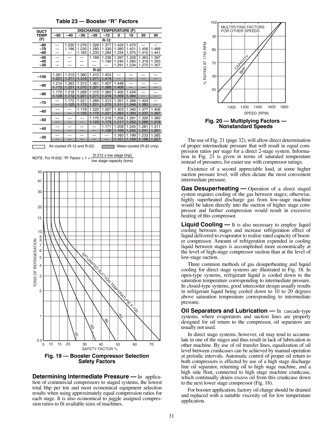
Fig. 20 — Multiplying Factors —
Nonstandard Speeds
The use of Fig. 21 (page 32), will allow direct determination of proper intermediate pressure that will result in equal com- pression ratios per stage for a direct
Existence of a second appreciable load, at some higher suction pressure level, will often dictate the most convenient intermediate pressure.
Gas Desuperheating — Operation of a direct staged system requires cooling of the gas between stages; otherwise, highly superheated discharge gas from
Liquid Cooling — It is also necessary to employ liquid cooling between stages and increase refrigeration effect of liquid delivered to evaporator to realize rated capacity of boost- er compressor. Amount of refrigeration expended in cooling liquid between stages is accomplished more economically at the level of
Three common methods of gas desuperheating and liquid cooling for direct stage systems are illustrated in Fig. 18. In
Oil Separators and Lubrication — In
In direct stage systems, however, oil may tend to accumu- late in one of the stages and thus result in lack of lubrication in other machine. By use of oil transfer lines, equalization of oil level between crankcases can be achieved by manual operation at periodic intervals. Automatic control of proper oil return to both compressors is effected by use of a high stage discharge line oil separator, returning oil to high stage machine, and a high side float, connected to high stage machine crankcase, which continually drains excess oil from this crankcase down to the next lower stage compressor (Fig. 18).
For booster application, factory oil charge should be drained and replaced with a suitable viscosity oil for low temperature application.
31