UL #4
UL #3
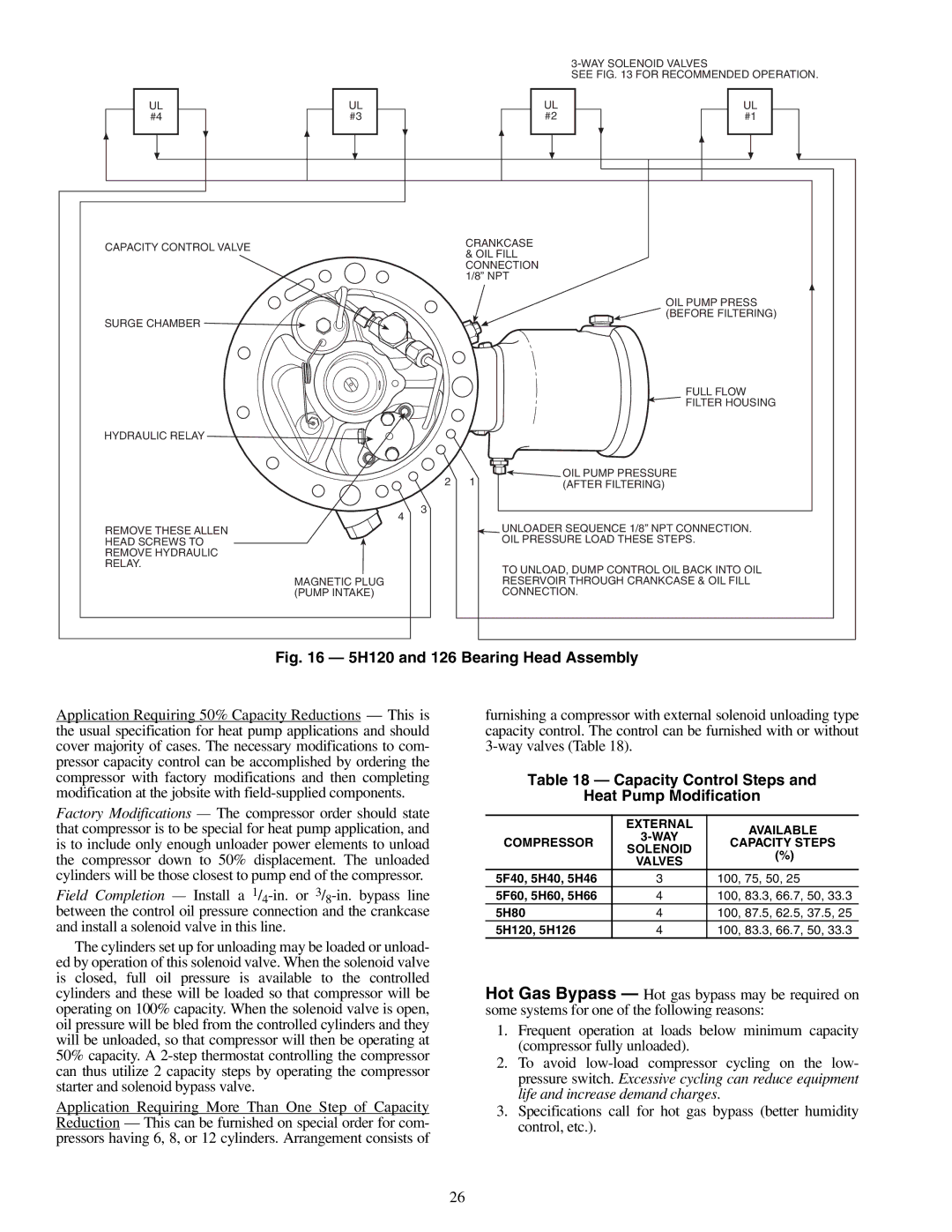
SEE FIG. 13 FOR RECOMMENDED OPERATION.
UL |
|
| UL |
| ||
#2 |
|
| #1 |
| ||
|
|
|
|
|
|
|
|
|
|
|
|
|
|
|
|
|
|
|
|
|
CAPACITY CONTROL VALVE | CRANKCASE | |
& OIL FILL | ||
| ||
| CONNECTION | |
| 1/8” NPT | |
| OIL PUMP PRESS | |
SURGE CHAMBER | (BEFORE FILTERING) | |
|
HYDRAULIC RELAY ![]()
4
FULL FLOW
![]() FILTER HOUSING
FILTER HOUSING
2 1 | OIL PUMP PRESSURE |
(AFTER FILTERING) |
3
REMOVE THESE ALLEN
HEAD SCREWS TO
REMOVE HYDRAULIC
RELAY.
MAGNETIC PLUG (PUMP INTAKE)
UNLOADER SEQUENCE 1/8” NPT CONNECTION. OIL PRESSURE LOAD THESE STEPS.
TO UNLOAD, DUMP CONTROL OIL BACK INTO OIL RESERVOIR THROUGH CRANKCASE & OIL FILL CONNECTION.
Fig. 16 — 5H120 and 126 Bearing Head Assembly
Application Requiring 50% Capacity Reductions — This is the usual specification for heat pump applications and should cover majority of cases. The necessary modifications to com- pressor capacity control can be accomplished by ordering the compressor with factory modifications and then completing modification at the jobsite with
Factory Modifications — The compressor order should state that compressor is to be special for heat pump application, and is to include only enough unloader power elements to unload the compressor down to 50% displacement. The unloaded cylinders will be those closest to pump end of the compressor.
Field Completion — Install a
The cylinders set up for unloading may be loaded or unload- ed by operation of this solenoid valve. When the solenoid valve is closed, full oil pressure is available to the controlled cylinders and these will be loaded so that compressor will be operating on 100% capacity. When the solenoid valve is open, oil pressure will be bled from the controlled cylinders and they will be unloaded, so that compressor will then be operating at 50% capacity. A
Application Requiring More Than One Step of Capacity Reduction — This can be furnished on special order for com- pressors having 6, 8, or 12 cylinders. Arrangement consists of
furnishing a compressor with external solenoid unloading type capacity control. The control can be furnished with or without
Table 18 — Capacity Control Steps and
Heat Pump Modification
| EXTERNAL | AVAILABLE | |
COMPRESSOR | |||
CAPACITY STEPS | |||
SOLENOID | |||
| (%) | ||
| VALVES | ||
|
| ||
5F40, 5H40, 5H46 | 3 | 100, 75, 50, 25 | |
5F60, 5H60, 5H66 | 4 | 100, 83.3, 66.7, 50, 33.3 | |
5H80 | 4 | 100, 87.5, 62.5, 37.5, 25 | |
5H120, 5H126 | 4 | 100, 83.3, 66.7, 50, 33.3 |
Hot Gas Bypass — Hot gas bypass may be required on some systems for one of the following reasons:
1.Frequent operation at loads below minimum capacity (compressor fully unloaded).
2.To avoid
3.Specifications call for hot gas bypass (better humidity control, etc.).
26