Table 4 Ð Relief Devices
STORAGE | RELIEF VALVE |
| REQUIRED FACTOR | ||
TANK SIZE | OUTLET SIZE | QUANTITY | lb air | Kg air | |
| min | min | |||
|
|
| |||
28 | 1 in. NPT | 2 | 31.4 | 14.2 | |
Female Connector | |||||
|
|
|
| ||
52 | 1 in. NPT | 2 | 52.3 | 23.7 | |
Female Connector | |||||
|
|
|
| ||
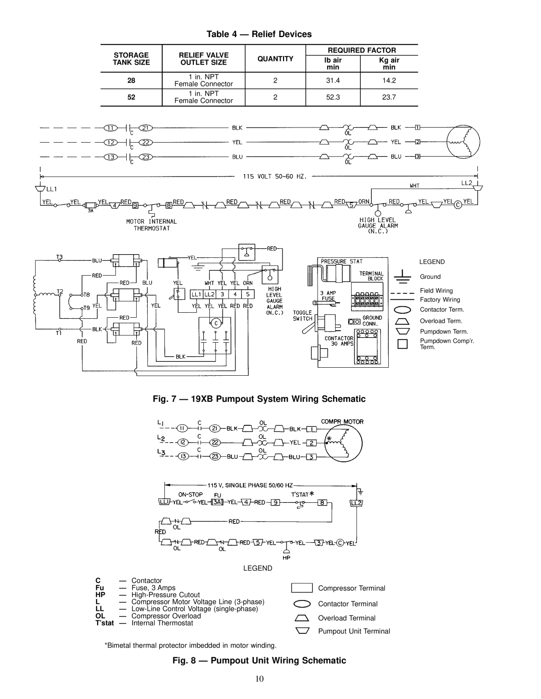
LEGEND
Ground
Field Wiring
Factory Wiring
Contactor Term.
Overload Term.
Pumpdown Term.
Pumpdown Comp'r.
Term.
Fig. 7 Ð 19XB Pumpout System Wiring Schematic
LEGEND
CÐ Contactor
Fu | Ð | Fuse, 3 Amps |
HP | Ð |
|
LÐ Compressor Motor Voltage Line
LL Ð
OL | Ð | Compressor Overload |
T'stat | Ð | Internal Thermostat |
*Bimetal thermal protector imbedded in motor winding.
Compressor Terminal
Contactor Terminal
Overload Terminal
Pumpout Unit Terminal
Fig. 8 Ð Pumpout Unit Wiring Schematic
10