VENT VALVE
VALVES
VALVES | CONTROL BOX | |
(WIRING BY | ||
| CONTRACTOR) | |
| COMPRESSOR | |
CONDENSER | REFRIGERANT | |
WATER | ||
INLET VALVE | ||
CONNECTIONS | ||
| ||
(FIELD PIPING) |
|
19EA PUMPOUT UNIT
19EA CONTROL BOX (INTERIOR)
19EA PUMPOUT UNITS
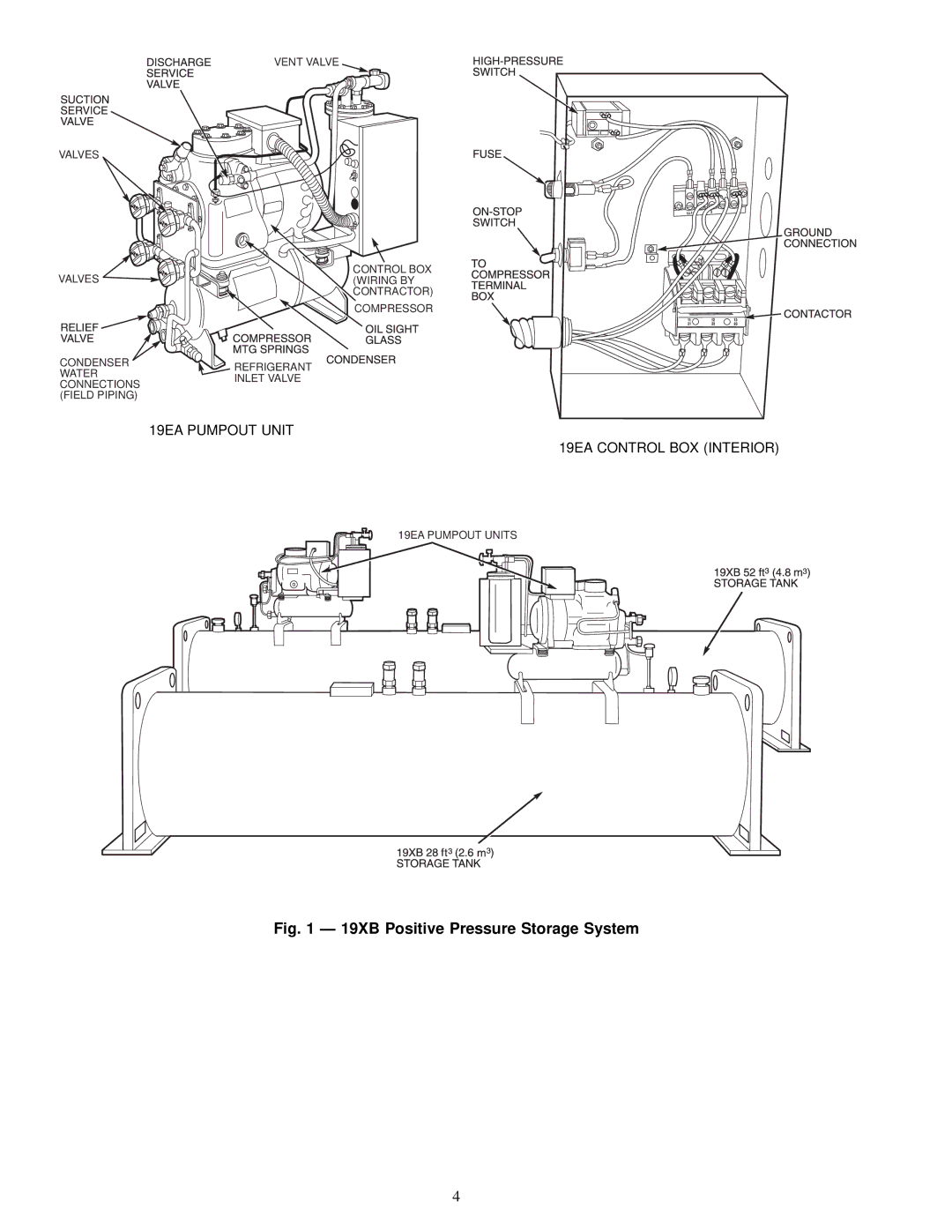
Fig. 1 Ð 19XB Positive Pressure Storage System
4