3. Remove any remaining refrigerant. a. Turn on chiller water pumps.
b. Turn on pumpout condenser water.
c. Place valves in the following positions:
VALVE | 1a | 1b | 2 | 3 | 4 | 5 | 6 | 7 | 8 | 10 | 11 |
CONDITION |
|
| C |
|
| C |
| C | C | C |
|
d. Run the pumpout compressor until the chiller pres- sure reaches 60 psig (414 kPa), [30 psig (207 kPa)]; then, shut off the pumpout compressor. Warm chiller condenser water will boil off any entrapped liquid re- frigerant and chiller pressure will rise.
e. When chiller pressure rises to 70 psig (483 kPa), [40 psig (276 kPa)]; turn on the pumpout compressor until the pressure again reaches 60 psig (414 kPa) [30 psig (207 kPa)]; then, turn off the pumpout com- pressor. Repeat this process until the chiller pressure no longer rises; then, turn on the pumpout compressor
and pump | out | until | the | chiller | pressure | reaches | |||||||||
18 in. Hg (41 kPa absolute). |
|
|
|
|
|
| |||||||||
f. Close valves 1a, 1b, 3, 4, and 6. |
|
|
|
|
|
| |||||||||
|
|
|
|
|
|
|
|
|
|
|
|
|
|
|
|
VALVE | 1a | 1b | 2 |
| 3 | 4 |
| 5 |
| 6 | 7 | 8 |
| 10 | 11 |
CONDITION | C | C | C |
| C | C |
| C |
| C | C | C |
| C |
|
g. Turn off the pumpout condenser water.
4. Establish vacuum for service. To conserve refrigerant, op- erate the pumpout compressor as described in Step 3e un- til the chiller pressure is reduced to 18 in. Hg (41 kPa absolute).
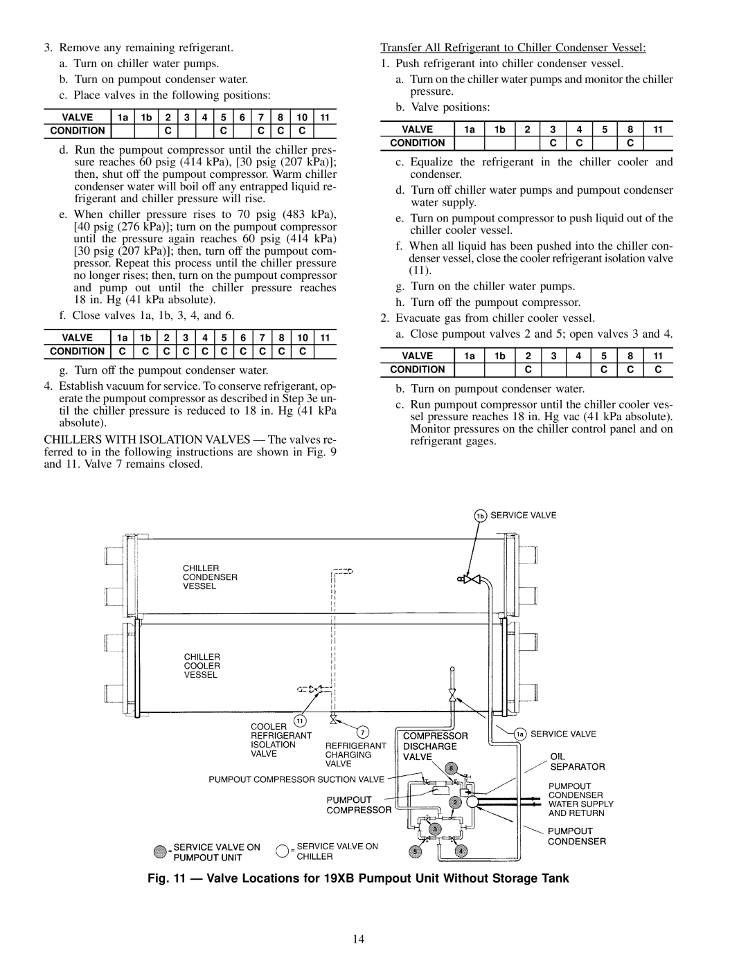
CHILLERS WITH ISOLATION VALVES Ð The valves re- ferred to in the following instructions are shown in Fig. 9 and 11. Valve 7 remains closed.
Transfer All Refrigerant to Chiller Condenser Vessel:
1. Push refrigerant into chiller condenser vessel.
a. Turn on the chiller water pumps and monitor the chiller pressure.
b. Valve positions:
VALVE | 1a | 1b | 2 | 3 | 4 | 5 | 8 | 11 |
CONDITION |
|
|
| C | C |
| C |
|
|
|
|
|
|
|
|
|
|
c. Equalize the refrigerant in the chiller cooler and condenser.
d. Turn off chiller water pumps and pumpout condenser water supply.
e. Turn on pumpout compressor to push liquid out of the chiller cooler vessel.
f. When all liquid has been pushed into the chiller con- denser vessel, close the cooler refrigerant isolation valve (11).
g. Turn on the chiller water pumps. h. Turn off the pumpout compressor.
2. Evacuate gas from chiller cooler vessel.
a. Close pumpout valves 2 and 5; open valves 3 and 4.
VALVE | 1a | 1b | 2 | 3 | 4 | 5 | 8 | 11 |
CONDITION |
|
| C |
|
| C | C | C |
b. Turn on pumpout condenser water.
c. Run pumpout compressor until the chiller cooler ves- sel pressure reaches 18 in. Hg vac (41 kPa absolute). Monitor pressures on the chiller control panel and on refrigerant gages.
Fig. 11 Ð Valve Locations for 19XB Pumpout Unit Without Storage Tank
14