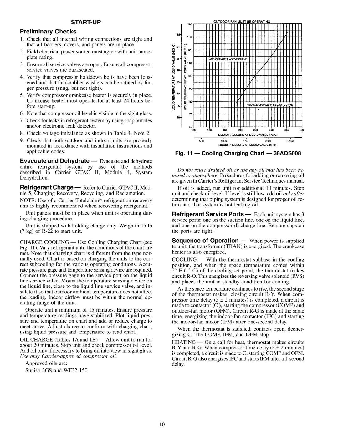
38AQS008 specifications
The Carrier 38AQS008 is a high-performance air conditioning unit that stands out for its innovative technology, design, and efficiency. As part of Carrier's extensive line of HVAC solutions, this model is engineered to deliver optimal indoor comfort while minimizing energy consumption.One of the main features of the Carrier 38AQS008 is its high SEER rating, which signifies exceptional energy efficiency. This rating ensures that consumers can enjoy lower utility bills and reduced environmental impact, making it an ideal choice for eco-conscious homeowners. The unit's advanced cooling technologies work seamlessly to maintain precise temperature control, ensuring a pleasant environment regardless of the season.
The Carrier 38AQS008 employs a variable-speed compressor, which allows the system to adjust its operation based on the cooling demand. Unlike traditional fixed-speed units that operate at a single speed, the variable-speed technology leads to quieter operation, increased efficiency, and improved dehumidification. As the unit operates at lower speeds, it can effectively reduce energy usage when full cooling capacity is not required, further enhancing overall efficiency.
In addition to its potent cooling capabilities, the Carrier 38AQS008 incorporates a robust filtration system that captures airborne particles, dust, and allergens. This feature not only improves indoor air quality but also ensures that the system operates efficiently by maintaining clean coils. Users can enjoy a healthier living space while also prolonging the lifespan of the air conditioning unit.
Another characteristic of the Carrier 38AQS008 is its durable construction, designed to withstand harsh weather conditions. The unit is equipped with a galvanized steel cabinet that offers corrosion resistance, and its compact design allows for easy installation and integration into various home environments.
Moreover, the Carrier 38AQS008 is compatible with smart home technology, allowing users to control their air conditioning system remotely. This feature enhances convenience and efficiency, as homeowners can adjust settings based on their daily routines and preferences.
Meeting rigorous energy performance standards, the Carrier 38AQS008 exemplifies Carrier's commitment to sustainability and customer satisfaction. With its combination of advanced features, reliable performance, and user-friendly technology, this air conditioning unit is a superior choice for those seeking a dependable and efficient cooling solution.

