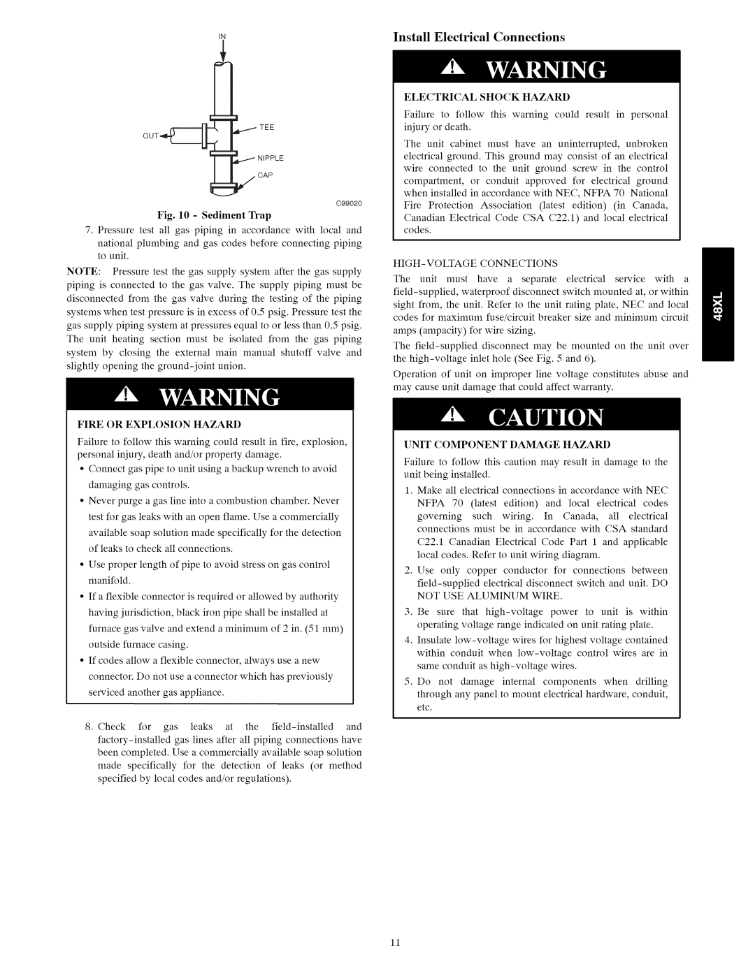
IN
TEE
CAP
C99020
Fig. 10 - Sediment Trap
7.Pressure test all gas piping in accordance with local and
national plumbing and gas codes before connecting piping to unit.
NOTE: | Pressure | test | the | gas | supply | system | after | the gas | supply | ||||
piping | is connected | to | the | gas | valve. | The | supply | piping | must | be | |||
disconnected | from | the | gas | valve during | the | testing | of | the | piping | ||||
systems | when | test | pressure | is in | excess | of 0.5 | psig. Pressure | test | the | ||||
gas supply piping system at pressures equal to or less than 0.5 psig.
The unit heating section must be isolated from the gas piping
system by closing the external main manual shutoff valve and
slightly opening the
FIRE OR EXPLOSION HAZARD
Failure to follow this warning could result in fire, explosion, personal injury, death and/or property damage.
•Connect gas pipe to unit using a backup wrench to avoid damaging gas controls.
•Never purge a gas line into a combustion chamber. Never test for gas leaks with an open flame. Use a commercially available soap solution made specifically for the detection of leaks to check all connections.
•Use proper length of pipe to avoid stress on gas control manifold.
•If a flexible connector is required or allowed by authority having jurisdiction, black iron pipe shall be installed at furnace gas valve and extend a minimum of 2 in. (51 mm) outside furnace casing.
•If codes allow a flexible connector, always use a new connector. Do not use a connector which has previously serviced another gas appliance.
8.Check for gas leaks at the
been completed. Use a commercially available soap solution
made specifically for the detection of leaks (or method specified by local codes and/or regulations).
Install Electrical Connections
ELECTRICAL SHOCK HAZARD
Failure to follow this warning could result in personal iniury or death.
The unit cabinet must have an uninterrupted, unbroken electrical ground. This ground may consist of an electrical
wire connected to the unit ground screw in the control
compartment, or conduit approved for electrical ground
when installed in accordance with NEC, NFPA 70 National
Fire Protection Association (latest edition) (in Canada,
Canadian Electrical Code CSA C22.1) and local electrical codes.
HIGH-VOLTAGE CONNECTIONS
The unit must have a separate electrical service with a
The
Operation of unit on improper line voltage constitutes abuse and may cause unit damage that could affect warranty.
UNIT COMPONENT DAMAGE HAZARD
Failure to follow this caution may result in damage to the unit being installed.
1.Make all electrical connections in accordance with NEC NFPA 70 (latest edition) and local electrical codes
governing such wiring. In Canada, all electrical connections must be in accordance with CSA standard
C22.1 Canadian Electrical Code Part 1 and applicable local codes. Refer to unit wiring diagram.
2.Use only copper conductor for connections between
3.Be sure that
4.Insulate
5.Do not damage internal components when drilling through any panel to mount electrical hardware, conduit, etc.
11