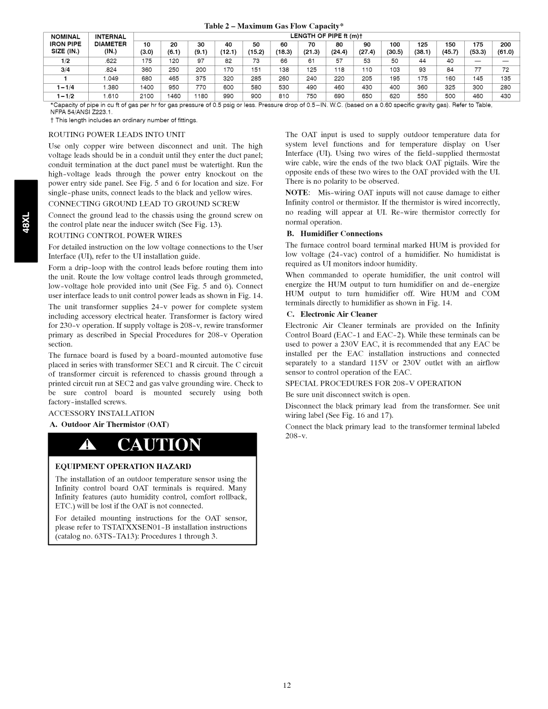
Table2- MaximumGas Flow Capacity*
NOMINAL | INTERNAL |
|
|
|
|
|
| LENGTH OF PIPE ft (m)'{" |
|
|
|
|
| |||
IRON PIPE | DIAMETER | 10 | 20 | 30 | 40 | 50 | 60 | 70 | 80 | 90 | 100 | 125 | 150 | 175 | 200 | |
SIZE (IN.) | (IN.) | (3.0) | (6.1) | (9.1) | (12.1) | (15.2) | (18.3) | (21.3) | (24.4) | (27.4) | (30.5) | (38.1) | (45.7) | (53.3) | (61.0) | |
| 1/2 | .622 | 175 | 120 | 97 | 82 | 73 | 66 | 61 | 57 | 53 | 50 | 44 | 40 | ||
| 3/4 | .824 | 360 | 250 | 200 | 170 | 151 | 138 | 125 | 118 | 110 | 103 | 93 | 84 | 77 | 72 |
| 1 | 1.049 | 680 | 465 | 375 | 320 | 285 | 260 | 240 | 220 | 205 | 195 | 175 | 160 | 145 | 135 |
1 | - 1/4 | 1.380 | 1400 | 950 | 770 | 600 | 580 | 530 | 490 | 460 | 430 | 400 | 360 | 325 | 300 | 280 |
1 | - 1/2 | 1.610 | 2100 | 1460 | 1180 | 990 | 900 | 810 | 750 | 690 | 650 | 620 | 550 | 500 | 460 | 430 |
*Capacity of pipe in cu ft of gas per hr for gas pressure of 0.5 psig or less. Pressure drop of
1- This length includes an ordinary number of fittings.
ROUTING POWER LEADS INTO UNIT
Use only copper wire between disconnect and unit. The high voltage leads should be in a conduit until they enter the duct panel;
conduit termination at the duct panel must be watertight. Run the
CONNECTING GROUND LEAD TO GROUND SCREW
Connect the ground lead to the chassis using the ground screw on the control plate near the inducer switch (See Fig. 13).
ROUTING CONTROL POWER WIRES
For detailed instruction on the low voltage connections to the User Interface (UI), refer to the UI installation guide.
Form a
The unit transformer supplies
including accessory electrical heater. Transformer is factory wired for
primary as described in Special Procedures for
The furnace board is fused by a
placed in series with transformer SEC1 and R circuit. The C circuit
of transformer circuit is referenced to chassis ground through a
printed circuit run at SEC2 and gas valve grounding wire. Check to
be sure control board is mounted securely using both
ACCESSORY INSTALLATION
A. Outdoor Air Thermistor (OAT)
EQUIPMENT OPERATION HAZARD
The installation of an outdoor temperature sensor using the
Infinity control board OAT terminals is required. Many
Infinity features (auto humidity control, comfort rollback, ETC.) will be lost if the OAT is not connected.
For detailed mounting instructions for the OAT sensor,
please refer to
(catalog no.
The OAT input is used to supply outdoor temperature data for
system level functions and for temperature display on User
Interface (UI). Using two wires of the
opposite ends of these two wires to the OAT provided with the UI. There is no polarity to be observed.
NOTE:
Infinity control or thermistor. If the thermistor is wired incorrectly,
no reading will appear at UI.
B. Humidifier Connections
The furnace control board terminal marked HUM is provided for
low voltage
When commanded to operate humidifier, the unit control will
energize the HUM output to turn humidifier on and
HUM output to turn humidifier off. Wire HUM and COM
terminals directly to humidifier as shown in Fig. 14.
C. Electronic Air Cleaner
Electronic Air Cleaner terminals are provided on the Infinity
Control Board
used to power a 230V EAC, it is recommended that any EAC be
installed per the EAC installation instructions and connected
separately to a standard II5V or 230V outlet with an airflow sensor to control operation of the EAC.
SPECIAL PROCEDURES FOR 208-V OPERATION
Be sure unit disconnect switch is open.
Disconnect the black primary lead from the transformer. See unit wiring label (See Fig. 16 and 17).
Connect the black primary lead to the transformer terminal labeled
12