Units with Factory-Installed Disconnect —

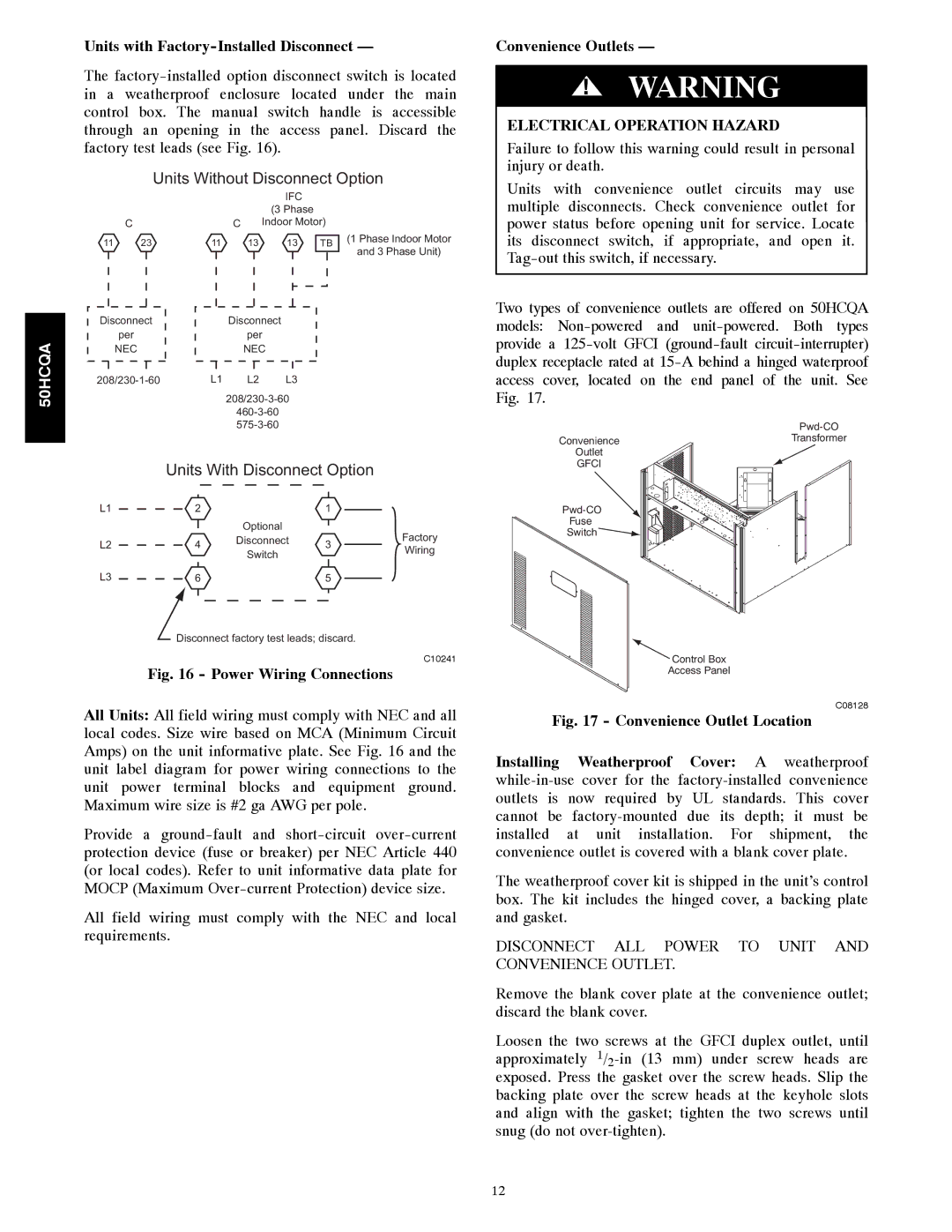
The factory-installed option disconnect switch is located in a weatherproof enclosure located under the main control box. The manual switch handle is accessible through an opening in the access panel. Discard the factory test leads (see Fig. 16).

Units Without Disconnect Option

Convenience Outlets —

!WARNING

ELECTRICAL OPERATION HAZARD

Failure to follow this warning could result in personal injury or death.

Units with convenience outlet circuits may use

50HCQA


IFC


(3 Phase


C

C


Indoor Motor)

11

23

11

13

13

TB

Disconnect


Disconnect


per


per


NEC


NEC


208/230-1-60


L1

L2

L3


208/230-3-60

460-3-60

575-3-60

(1 Phase Indoor Motor

and 3 Phase Unit)

multiple disconnects. Check convenience outlet for power status before opening unit for service. Locate its disconnect switch, if appropriate, and open it. Tag-out this switch, if necessary.

Two types of convenience outlets are offered on 50HCQA models: Non-powered and unit-powered. Both types provide a 125-volt GFCI (ground-fault circuit-interrupter) duplex receptacle rated at 15-A behind a hinged waterproof access cover, located on the end panel of the unit. See Fig. 17.


Pwd-CO

Convenience

Transformer

Outlet


GFCI


Units With Disconnect Option

L1

2


1


Optional


Factory

L2

4

Disconnect

3

Switch

Wiring


L3

6


5


Disconnect factory test leads; discard.

C10241

Fig. 16 - Power Wiring Connections

All Units: All field wiring must comply with NEC and all local codes. Size wire based on MCA (Minimum Circuit Amps) on the unit informative plate. See Fig. 16 and the unit label diagram for power wiring connections to the unit power terminal blocks and equipment ground. Maximum wire size is #2 ga AWG per pole.

Provide a ground-fault and short-circuit over-current protection device (fuse or breaker) per NEC Article 440 (or local codes). Refer to unit informative data plate for MOCP (Maximum Over-current Protection) device size.

All field wiring must comply with the NEC and local requirements.

Pwd-CO

Fuse

Switch

Control Box

Access Panel

C08128

Fig. 17 - Convenience Outlet Location

Installing Weatherproof Cover: A weatherproof while-in-use cover for the factory-installed convenience outlets is now required by UL standards. This cover cannot be factory-mounted due its depth; it must be installed at unit installation. For shipment, the convenience outlet is covered with a blank cover plate.

The weatherproof cover kit is shipped in the unit’s control box. The kit includes the hinged cover, a backing plate and gasket.

DISCONNECT ALL POWER TO UNIT AND CONVENIENCE OUTLET.

Remove the blank cover plate at the convenience outlet; discard the blank cover.

Loosen the two screws at the GFCI duplex outlet, until approximately 1/2-in (13 mm) under screw heads are exposed. Press the gasket over the screw heads. Slip the backing plate over the screw heads at the keyhole slots and align with the gasket; tighten the two screws until snug (do not over-tighten).

12

Page 12
Image 12
Carrier 50HCQA installation instructions Units with Factory-Installed Disconnect, Convenience Outlets

50HCQA specifications

The Carrier 50HCQA is a cutting-edge rooftop air conditioning unit designed for commercial applications, combining efficiency, reliability, and advanced technology to ensure optimal indoor climate control. This model stands out in Carrier's extensive range of HVAC solutions, showcasing a blend of innovative features suitable for diverse building types.

One of the key features of the Carrier 50HCQA is its high-efficiency compressor. With variable-speed capabilities, the compressor adjusts its output to meet the precise cooling or heating demands of the space, promoting energy savings and consistent temperature management. This flexibility results in reduced energy consumption, making the 50HCQA an environmentally friendly choice for businesses looking to lower their carbon footprint.

The 50HCQA integrates advanced microprocessor controls, streamlining operation and enhancing user interaction. This technology allows for sophisticated diagnostics, monitoring, and scheduling, giving facility managers the tools they need to optimize system performance. The user-friendly interface ensures that settings can be easily adjusted, and real-time performance metrics can be accessed to ensure efficient operation.

In terms of construction, the Carrier 50HCQA is built with durability in mind. The unit features a robust cabinet design with a galvanized steel construction that is resistant to corrosion. This feature enhances the longevity of the unit, making it suitable for a variety of weather conditions. Additionally, the insulated casing reduces sound levels, providing a quieter operation that is particularly beneficial in noise-sensitive environments.

Another significant characteristic of the 50HCQA is its environmentally responsible refrigerant options. It utilizes R-410A refrigerant, which has a lower Global Warming Potential (GWP) compared to traditional refrigerants. This aspect not only meets regulatory standards but also supports users in making eco-friendly choices in their HVAC systems.

The 50HCQA also supports a range of optional accessories, including economizers for enhanced energy efficiency and improved air quality. This allows for increased outdoor air intake during suitable conditions, which can significantly contribute to enhancing indoor air quality—an essential factor for occupant comfort and health.

In conclusion, the Carrier 50HCQA is an exemplary model in the commercial HVAC sector, delivering powerful performance, advanced control technologies, and robust construction. Its energy-efficient design, user-friendly controls, and eco-conscious refrigerant options make it a top choice for businesses aiming to invest in sustainable and reliable climate control solutions.