concealed below ground. The number of loops required de- pends on ground conditions, heating and cooling require- ments, and the depth of each hole.
Hybrid systems — In some applications, it may be bene- ficial to incorporate a cooling tower into the ground loop system to reduce the overall cost. A Hybrid System dis- cards excess heat into the air and increases the cooling performance of the ground loop.
Condensate drainage
Connect the console unit condensate drain to the building condensate drain with a flexible,
Installing a trap or drain in the field is not required unless specified by local codes. The 50KQL units are designated in a
Water conditioning
In some applications, maintaining proper water quality may require higher corrosion protection for the
1.Scale formation caused by hard water reduces the heat transfer rate and increases the water pressure drop through the heat exchanger. As water is heated, minerals and salts are precipitated from a solution and deposited on the inside surface of the pipe or tube.
2.Corrosion is caused by absorption of gases from the air coupled with water on exposed metal. Corrosion is also common in
3.Organic growths, such as algae, can reduce the heat transfer rate by forming an insulating coating on the inside tube surface. Algae can also promote corrosion by pitting.
NOTE: In most commercial water loop applications, Aqua- zone™ WSHP units use copper
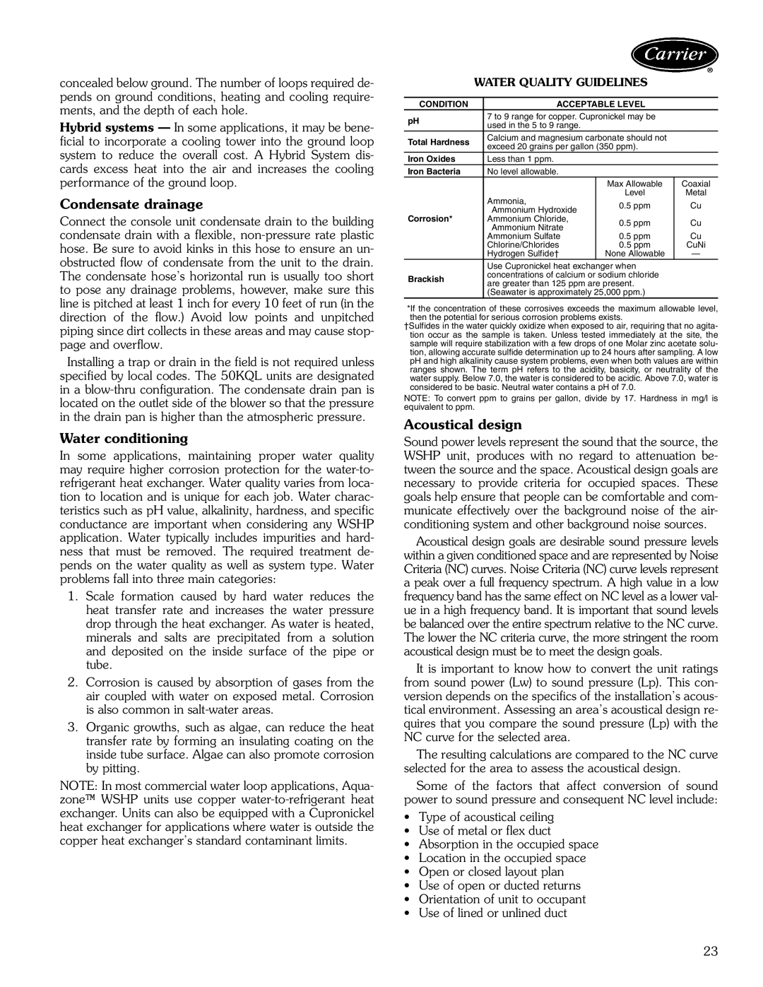
| WATER QUALITY GUIDELINES |
| ||
|
|
|
|
|
CONDITION |
| ACCEPTABLE LEVEL |
| |
pH |
| 7 to 9 range for copper. Cupronickel may be |
| |
| used in the 5 to 9 range. |
|
| |
|
|
|
| |
Total Hardness |
| Calcium and magnesium carbonate should not |
| |
| exceed 20 grains per gallon (350 ppm). |
| ||
|
|
| ||
Iron Oxides |
| Less than 1 ppm. |
|
|
Iron Bacteria |
| No level allowable. |
|
|
|
|
| Max Allowable | Coaxial |
|
| Ammonia, | Level | Metal |
|
| 0.5 ppm | Cu | |
|
| Ammonium Hydroxide | ||
Corrosion* |
|
|
| |
| Ammonium Chloride, | 0.5 ppm | Cu | |
|
| Ammonium Nitrate | ||
|
|
|
| |
|
| Ammonium Sulfate | 0.5 ppm | Cu |
|
| Chlorine/Chlorides | 0.5 ppm | CuNi |
|
| Hydrogen Sulfide† | None Allowable | — |
|
| Use Cupronickel heat exchanger when |
| |
Brackish |
| concentrations of calcium or sodium chloride |
| |
| are greater than 125 ppm are present. |
| ||
|
|
| ||
|
| (Seawater is approximately 25,000 ppm.) |
| |
*If the concentration of these corrosives exceeds the maximum allowable level, then the potential for serious corrosion problems exists.
†Sulfides in the water quickly oxidize when exposed to air, requiring that no agita- tion occur as the sample is taken. Unless tested immediately at the site, the sample will require stabilization with a few drops of one Molar zinc acetate solu- tion, allowing accurate sulfide determination up to 24 hours after sampling. A low pH and high alkalinity cause system problems, even when both values are within ranges shown. The term pH refers to the acidity, basicity, or neutrality of the water supply. Below 7.0, the water is considered to be acidic. Above 7.0, water is considered to be basic. Neutral water contains a pH of 7.0.
NOTE: To convert ppm to grains per gallon, divide by 17. Hardness in mg/l is equivalent to ppm.
Acoustical design
Sound power levels represent the sound that the source, the WSHP unit, produces with no regard to attenuation be- tween the source and the space. Acoustical design goals are necessary to provide criteria for occupied spaces. These goals help ensure that people can be comfortable and com- municate effectively over the background noise of the air- conditioning system and other background noise sources.
Acoustical design goals are desirable sound pressure levels within a given conditioned space and are represented by Noise Criteria (NC) curves. Noise Criteria (NC) curve levels represent a peak over a full frequency spectrum. A high value in a low frequency band has the same effect on NC level as a lower val- ue in a high frequency band. It is important that sound levels be balanced over the entire spectrum relative to the NC curve. The lower the NC criteria curve, the more stringent the room acoustical design must be to meet the design goals.
It is important to know how to convert the unit ratings from sound power (Lw) to sound pressure (Lp). This con- version depends on the specifics of the installation’s acous- tical environment. Assessing an area’s acoustical design re- quires that you compare the sound pressure (Lp) with the NC curve for the selected area.
The resulting calculations are compared to the NC curve selected for the area to assess the acoustical design.
Some of the factors that affect conversion of sound power to sound pressure and consequent NC level include:
•Type of acoustical ceiling
•Use of metal or flex duct
•Absorption in the occupied space
•Location in the occupied space
•Open or closed layout plan
•Use of open or ducted returns
•Orientation of unit to occupant
•Use of lined or unlined duct
23