Typical wiring schematics (cont)
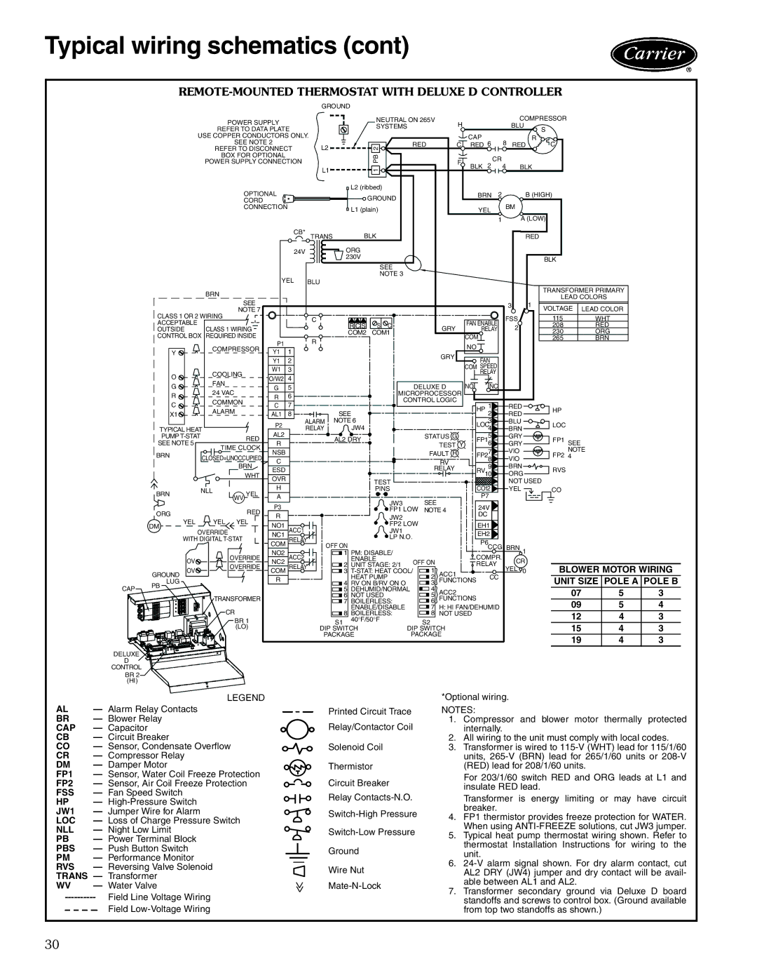
REMOTE-MOUNTED THERMOSTAT WITH DELUXE D CONTROLLER
CAP
DELUXE
D
CONTROL
BR 2
(HI)
|
|
|
|
|
| GROUND |
|
|
|
|
|
|
|
|
|
|
|
| ||
|
| POWER SUPPLY |
|
|
|
| NEUTRAL ON 265V | H |
|
|
| COMPRESSOR |
|
| ||||||
|
|
|
|
|
| SYSTEMS |
|
|
|
|
| BLU |
|
|
|
| ||||
|
| REFER TO DATA PLATE |
|
|
|
|
|
|
|
|
| S |
|
| ||||||
|
|
|
|
|
|
|
|
|
|
|
|
|
|
|
| |||||
|
| USE COPPER CONDUCTORS ONLY. |
|
|
|
|
|
| CAP |
|
|
| R |
|
|
| ||||
|
| SEE NOTE 2 |
| L2 |
|
| 2 | RED | C | RED 6 | 8 | RED |
| C |
|
| ||||
|
| REFER TO DISCONNECT |
|
|
|
|
|
|
|
|
|
|
|
|
| |||||
|
| BOX FOR OPTIONAL |
|
|
|
| PB |
|
|
|
| CR |
|
|
|
|
|
| ||
|
| POWER SUPPLY CONNECTION |
|
|
|
|
| F |
|
|
|
|
|
|
| |||||
|
|
|
|
|
|
|
| BLK | 2 | 4 | BLK |
|
|
| ||||||
|
|
|
|
|
| L1 |
|
| 1 |
|
|
|
|
|
| |||||
|
|
| OPTIONAL |
|
|
| L2 (ribbed) |
|
|
| BRN 2 |
| B (HIGH) |
|
| |||||
|
|
|
|
|
|
| GROUND |
|
|
|
|
|
| |||||||
|
|
| CORD |
|
|
|
|
|
|
|
|
|
| BM |
|
|
|
| ||
|
|
| CONNECTION |
|
|
| L1 (plain) |
|
|
| YEL |
|
|
|
| |||||
|
|
|
|
|
|
|
|
|
|
|
|
|
|
|
|
| ||||
|
|
|
|
|
|
|
|
|
|
|
|
|
| 1 |
| A (LOW) |
|
| ||
|
|
|
|
| CB* | TRANS |
| BLK |
|
|
|
|
|
| RED |
|
|
| ||
|
|
|
|
| 24V |
|
| ORG |
|
|
|
|
|
|
|
|
|
|
|
|
|
|
|
|
|
|
|
| 230V |
|
|
|
|
|
|
|
|
| BLK |
|
|
|
|
|
|
|
|
|
|
| SEE |
|
|
|
|
|
|
|
|
|
|
|
|
|
|
| YEL |
|
|
| NOTE 3 |
|
|
|
|
|
|
|
|
|
|
| |
|
|
|
| BLU |
|
|
|
|
|
|
|
|
|
|
|
|
|
| ||
|
| BRN |
|
|
|
|
|
|
|
|
|
|
|
|
|
|
| TRANSFORMER PRIMARY |
| |
|
|
|
|
|
|
|
|
|
|
|
|
|
|
|
|
| LEAD COLORS |
| ||
|
| SEE |
|
|
|
|
|
|
|
|
|
|
|
|
|
|
| |||
|
|
|
|
|
|
|
|
|
|
|
|
|
| 3 | 1 | VOLTAGE | LEAD COLOR |
| ||
|
| NOTE 7 |
|
|
|
|
|
|
|
|
|
|
|
|
|
|
| |||
CLASS 1 OR 2 WIRING |
|
|
| C |
|
|
|
|
|
|
|
| FSS |
| 115 | WHT |
| |||
ACCEPTABLE |
|
|
|
|
|
|
|
|
|
| FAN ENABLE |
|
| |||||||
|
|
|
|
|
| R C S | S C |
|
| GRY |
| 2 |
| 208 | RED |
| ||||
OUTSIDE | CLASS 1 WIRING |
|
|
|
|
|
| RELAY |
|
|
| |||||||||
|
|
|
| COM2 | COM1 |
|
|
|
| 230 | ORG |
| ||||||||
CONTROL BOX REQUIRED INSIDE |
|
|
|
|
|
|
| COM |
|
|
|
|
| |||||||
P1 |
| R |
|
|
|
|
|
|
|
|
|
| 265 | BRN |
| |||||
|
|
|
|
|
|
|
|
|
|
| NO |
|
|
|
|
|
|
| ||
|
| COMPRESSOR |
|
|
|
|
|
|
|
|
|
|
|
|
|
|
| |||
Y |
| Y1 | 1 |
|
|
|
|
|
|
|
|
|
|
|
|
|
| |||
|
|
|
|
|
|
|
|
|
|
|
|
|
|
|
| |||||
|
|
|
|
|
|
|
|
| GRY |
|
|
|
|
|
|
|
| |||
|
|
|
| Y1 | 2 |
|
|
|
|
|
| FAN |
|
|
|
|
|
| ||
|
|
|
|
|
|
|
|
|
|
|
|
|
|
|
|
| ||||
|
|
|
| W1 | 3 |
|
|
|
|
|
|
| COM SPEED |
|
|
|
|
|
| |
|
| COOLING |
|
|
|
|
|
|
|
| RELAY |
|
|
|
|
|
| |||
O |
|
| O/W2 | 4 |
|
|
|
|
|
|
|
|
|
|
|
|
| |||
| FAN |
|
|
|
|
|
|
|
|
|
|
|
|
|
|
|
| |||
G |
|
| G | 5 |
|
|
|
| DELUXE D | NO | NC |
|
|
|
|
|
| |||
| 24 VAC |
|
|
|
|
|
|
|
|
|
|
| ||||||||
R |
|
| R | 6 |
|
|
| MICROPROCESSOR |
|
|
|
|
|
|
|
| ||||
| COMMON |
|
|
|
| CONTROL LOGIC |
|
|
|
|
|
|
|
| ||||||
C |
|
| C | 7 |
|
|
|
| 1 |
| RED |
|
|
|
| |||||
|
|
|
|
|
|
|
|
| HP |
|
|
|
|
| ||||||
| ALARM |
|
|
|
|
|
|
|
|
|
| HP |
|
| ||||||
X1 |
|
| 8 |
| SEE |
|
|
|
|
|
|
|
| |||||||
|
|
| AL1 |
|
|
|
|
|
| 2 |
| RED |
|
|
|
| ||||
|
|
|
|
| ALARM | NOTE 6 |
|
|
|
|
| 3 |
| BLU |
|
|
|
| ||
TYPICAL HEAT |
| P2 | RELAY |
| JW4 |
|
|
|
| LOC4 |
| BRN |
| LOC |
|
| ||||
PUMP | RED | AL2 |
|
| AL2 DRY |
|
| STATUS G |
| 5 |
| GRY |
|
|
|
| ||||
SEE NOTE 5 |
| R |
|
|
|
|
| TEST Y | FP16 |
| GRY |
| FP1 SEE |
|
| |||||
TIME CLOCK |
|
|
|
|
|
|
|
|
| |||||||||||
|
| NSB |
|
|
|
|
|
| FAULT R |
| 7 |
| VIO |
| NOTE |
| ||||
BRN |
| CLOSED=UNOCCUPIED |
|
|
|
|
|
|
|
|
| FP2 4 |
|
| ||||||
| C |
|
|
|
|
|
|
| RV | FP28 |
| VIO |
|
|
| |||||
|
| BRN |
|
|
|
|
|
|
|
| 9 |
| BRN |
|
|
|
| |||
|
| ESD |
|
|
|
|
|
| RELAY |
|
|
| RVS |
|
| |||||
|
|
| WHT |
|
|
|
|
|
| RV10 |
| ORG |
|
|
| |||||
|
|
|
|
|
|
|
|
|
|
|
|
|
|
| ||||||
|
|
|
| OVR |
|
|
|
| TEST |
|
|
|
|
|
| NOT USED |
|
| ||
BRN |
| NLL | YEL | H |
|
|
|
| PINS |
|
|
| CO12 |
| YEL |
| CO |
|
| |
| WV | A |
|
|
|
| JW3 |
| SEE |
| P7 |
|
|
|
|
|
| |||
|
|
|
| P3 |
|
|
|
|
|
| 24V |
|
|
|
|
|
| |||
ORG |
|
| RED |
|
|
|
| FP1 LOW | NOTE 4 |
|
|
|
|
|
| |||||
|
| R |
|
|
|
| DC |
|
|
|
|
|
|
| ||||||
|
|
|
|
|
| JW2 |
|
|
|
|
|
|
|
|
|
| ||||
| YEL | YEL YEL |
|
|
|
|
|
|
|
|
|
|
|
|
|
|
| |||
DM | NO1 |
|
|
|
| FP2 LOW |
|
| EH1 |
|
|
|
|
|
| |||||
|
|
|
|
|
|
|
|
|
|
|
|
|
|
| ||||||
|
| OVERRIDE |
| NC1 ACC1 |
|
|
| JW1 |
|
|
| EH2 |
|
|
|
|
|
| ||
| WITH DIGITAL |
| COM RELAY | OFF ON | LP N.O. |
|
| P6 |
|
|
|
|
|
| ||||||
|
|
|
|
|
|
|
|
|
|
|
| |||||||||
|
| OVERRIDE | NO2 | ACC2 |
|
| 1 PM: DISABLE/ |
|
|
|
| CCG BRN 1 |
|
|
|
| ||||
| OV | NC2 |
|
| ENABLE | OFF ON |
| COMPR. |
| CR |
|
|
|
| ||||||
|
|
|
|
|
| 2 UNIT STAGE: 2/1 |
| RELAY |
|
|
|
|
| |||||||
| OV | OVERRIDE | COM RELAY |
|
|
| 1 |
| YEL 0 |
| BLOWER MOTOR WIRING | |||||||||
GROUND |
|
| 3 | ACC1 |
|
|
| |||||||||||||
|
|
| R |
|
|
| HEAT PUMP |
| 2 |
| CC |
|
|
| UNIT SIZE POLE A POLE B | |||||
LUG |
|
|
|
|
|
| 4 RV ON B/RV ON O |
| 3 | FUNCTIONS |
|
|
|
| ||||||
PB |
|
|
|
|
|
|
| 5 DEHUMID/NORMAL |
| 4 | ACC2 |
|
|
|
|
| 07 | 5 | 3 | |
|
|
|
|
|
|
|
| 6 NOT USED |
| 5 |
|
|
|
|
| |||||
|
| TRANSFORMER |
|
|
|
| 7 BOILERLESS: |
| 6 | FUNCTIONS |
|
|
|
| 09 | 5 | 4 | |||
|
| CR |
|
|
|
|
| ENABLE/DISABLE |
| 7 | H: HI FAN/DEHUMID |
|
|
| ||||||
|
|
|
|
|
|
| 8 BOILERLESS: |
| 8 NOT USED |
|
|
|
| 12 | 4 | 3 | ||||
|
| BR 1 |
|
|
| S1 | 40°F/50°F |
| S2 |
|
|
|
|
|
| |||||
|
|
|
|
|
|
|
|
|
|
|
|
|
| 15 | 4 | 3 | ||||
|
| (LO) |
|
| DIP SWITCH | DIP SWITCH |
|
|
|
|
| |||||||||
|
|
|
|
|
| PACKAGE |
| PACKAGE |
|
|
|
|
| 19 | 4 | 3 | ||||
|
|
|
|
|
|
|
|
|
|
|
|
|
|
|
|
|
| |||
| LEGEND |
AL | — Alarm Relay Contacts |
BR | — Blower Relay |
CAP | — Capacitor |
CB | — Circuit Breaker |
CO | — Sensor, Condensate Overflow |
CR | — Compressor Relay |
DM | — Damper Motor |
FP1 | — Sensor, Water Coil Freeze Protection |
FP2 | — Sensor, Air Coil Freeze Protection |
FSS | — Fan Speed Switch |
HP | — |
JW1 | — Jumper Wire for Alarm |
LOC | — Loss of Charge Pressure Switch |
NLL | — Night Low Limit |
PB | — Power Terminal Block |
PBS | — Push Button Switch |
PM | — Performance Monitor |
RVS | — Reversing Valve Solenoid |
TRANS | — Transformer |
WV | — Water Valve |
Field Line Voltage Wiring | |
| Field |
>>
Printed Circuit Trace Relay/Contactor Coil
Solenoid Coil
Thermistor
Circuit Breaker
Relay
Ground
Wire Nut
*Optional wiring.
NOTES:
1.Compressor and blower motor thermally protected internally.
2.All wiring to the unit must comply with local codes.
3.Transformer is wired to
For 203/1/60 switch RED and ORG leads at L1 and insulate RED lead.
Transformer is energy limiting or may have circuit breaker.
4.FP1 thermistor provides freeze protection for WATER. When using
5.Typical heat pump thermostat wiring shown. Refer to thermostat Installation Instructions for wiring to the unit.
6.
7.Transformer secondary ground via Deluxe D board standoffs and screws to control box. (Ground available from top two standoffs as shown.)
30