Typical piping
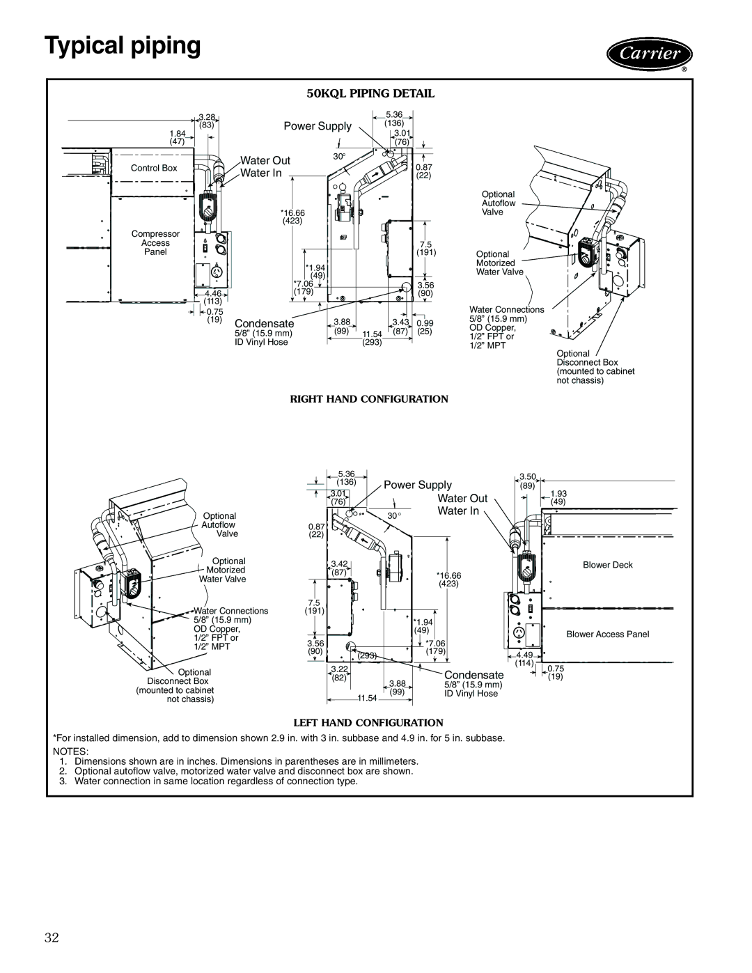
50KQL PIPING DETAIL
3.28
(83)
1.84
(47)
Control Box
Compressor
Access
Panel
![]() 4.46
4.46![]() (113)
(113)
![]() 0.75 (19)
0.75 (19)
|
| 5.36 |
|
| |
Power Supply | (136) |
|
| ||
|
| 3.01 |
|
| |
|
| (76) |
|
| |
Water Out | 30° |
|
|
| |
|
| 0.87 |
| ||
Water In |
|
|
| ||
|
| (22) |
| ||
|
|
|
| Optional | |
|
|
|
| Autoflow | |
*16.66 |
|
|
| Valve | |
(423) |
|
|
|
| |
|
|
| 7.5 |
| |
|
|
| (191) | Optional | |
*1.94 |
|
|
| Motorized | |
|
|
| Water Valve | ||
(49) |
|
|
| ||
*7.06 |
|
| 3.56 |
| |
(179) |
|
| (90) |
| |
|
|
|
| Water Connections | |
Condensate | 3.88 | 3.43 | 0.99 | 5/8” (15.9 mm) | |
OD Copper, | |||||
5/8” (15.9 mm) | (99) | 11.54 (87) | (25) | ||
1/2” FPT or | |||||
ID Vinyl Hose |
| (293) |
| ||
|
| 1/2” MPT | |||
|
|
|
| ||
Optional Disconnect Box (mounted to cabinet not chassis)
RIGHT HAND CONFIGURATION
| 5.36 |
|
| 3.50 | |
| (136) | Power Supply | |||
| (89) | ||||
| 3.01 |
| Water Out |
| |
| (76) |
|
| ||
Optional |
| 30° | Water In |
| |
|
|
| |||
Autoflow | 0.87 |
|
|
| |
Valve | (22) |
|
|
| |
Optional | 3.42 |
|
|
| |
Motorized |
|
|
| ||
(87) |
| *16.66 |
| ||
Water Valve |
|
|
| ||
|
| (423) |
| ||
|
|
|
| ||
Water Connections | 7.5 |
|
|
| |
(191) |
|
|
| ||
5/8” (15.9 mm) |
|
| *1.94 |
| |
OD Copper, |
|
| (49) |
| |
1/2” FPT or | 3.56 |
| *7.06 |
| |
1/2” MPT |
|
| |||
(90) | (293) | (179) | 4.49 | ||
| |||||
|
|
| |||
Optional | 3.22 |
|
| (114) | |
| Condensate |
| |||
(82) |
|
| |||
Disconnect Box |
| 3.88 | 5/8” (15.9 mm) |
| |
(mounted to cabinet |
|
| |||
| (99) | ID Vinyl Hose |
| ||
not chassis) |
| 11.54 |
|
| |
1.93
(49)
Blower Deck
Blower Access Panel
0.75
(19)
LEFT HAND CONFIGURATION
*For installed dimension, add to dimension shown 2.9 in. with 3 in. subbase and 4.9 in. for 5 in. subbase.
NOTES:
1.Dimensions shown are in inches. Dimensions in parentheses are in millimeters.
2.Optional autoflow valve, motorized water valve and disconnect box are shown.
3.Water connection in same location regardless of connection type.
32
