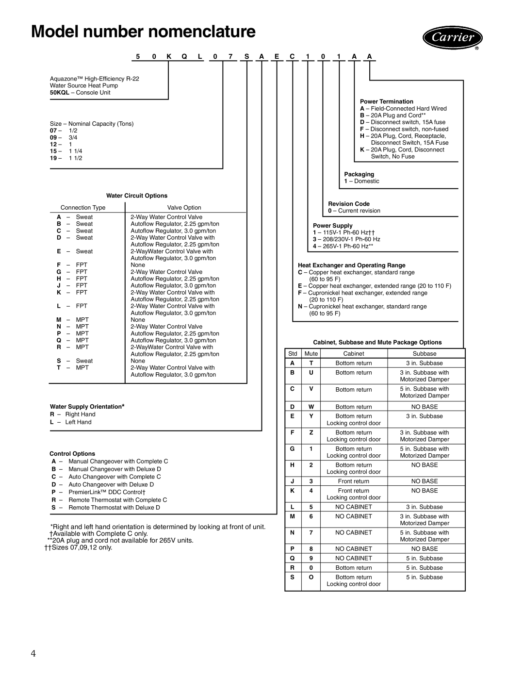
Model number nomenclature
5 0 K Q L 0 7 S A E C 1 0 1 A A
Aquazone™
Size – Nominal Capacity (Tons)
07 – | 1/2 |
|
|
|
| ||
09 – | 3/4 |
|
|
|
| ||
12 – | 1 |
|
|
|
|
| |
15 – | 1 1/4 |
|
|
|
| ||
19 – | 1 1/2 |
|
|
|
| ||
|
|
|
|
|
|
|
|
|
|
|
| Water Circuit Options |
|
| |
| Connection Type |
| Valve Option |
|
| ||
|
|
|
| ||||
|
|
|
|
|
|
|
|
| A | – | Sweat |
|
|
| |
| B | – | Sweat |
| Autoflow Regulator, 2.25 gpm/ton |
|
|
| C | – | Sweat |
| Autoflow Regulator, 3.0 gpm/ton |
|
|
| D | – | Sweat |
|
|
| |
| E |
|
|
| Autoflow Regulator, 2.25 gpm/ton |
|
|
| – | Sweat |
|
|
| ||
| F |
|
|
| Autoflow Regulator, 3.0 gpm/ton |
|
|
| – | FPT |
| None |
|
| |
| G | – | FPT |
|
|
| |
| H | – | FPT |
| Autoflow Regulator, 2.25 gpm/ton |
|
|
| J | – | FPT |
| Autoflow Regulator, 3.0 gpm/ton |
|
|
| K | – | FPT |
|
|
| |
| L |
|
|
| Autoflow Regulator, 2.25 gpm/ton |
|
|
| – | FPT |
|
|
| ||
| M – |
|
| Autoflow Regulator, 3.0 gpm/ton |
|
| |
| MPT |
| None |
|
| ||
| N | – | MPT |
|
|
| |
| P | – | MPT |
| Autoflow Regulator, 2.25 gpm/ton |
|
|
| Q | – | MPT |
| Autoflow Regulator, 3.0 gpm/ton |
|
|
| R | – | MPT |
|
|
| |
| S |
|
|
| Autoflow Regulator, 2.25 gpm/ton |
|
|
| – | Sweat |
| None |
|
| |
| T | – | MPT |
|
|
| |
|
|
|
|
| Autoflow Regulator, 3.0 gpm/ton |
|
|
|
|
|
|
|
|
|
|
Water Supply Orientation*
R – Right Hand
L – Left Hand
Control Options
A– Manual Changeover with Complete C
B– Manual Changeover with Deluxe D
C– Auto Changeover with Complete C
D– Auto Changeover with Deluxe D
P – PremierLink™ DDC Control†
R– Remote Thermostat with Complete C
S– Remote Thermostat with Deluxe D
*Right and left hand orientation is determined by looking at front of unit. * Right and left hand orientation is determined by looking at front of unit. †Available with Complete C only.
† For these options, unit must be hard wired (digit 15 must be “A”). **20A plug and cord not available for 265V units.
††Sizes 07,09,12 only.
Power Termination
A –
B – 20A Plug and Cord**
D – Disconnect switch, 15A fuse
F – Disconnect switch,
H – 20A Plug, Cord, Receptacle,
Disconnect Switch, 15A Fuse
K – 20A Plug, Cord, Disconnect
Switch, No Fuse
Packaging
1 – Domestic
Revision Code
0 – Current revision
Power Supply
1 –
3 –
4 –
Heat Exchanger and Operating Range
C – Copper heat exchanger, standard range (60 to 95 F)
E – Copper heat exchanger, extended range (20 to 110 F) F – Cupronickel heat exchanger, extended range
(20 to 110 F)
N – Cupronickel heat exchanger, standard range (60 to 95 F)
Cabinet, Subbase and Mute Package Options
Std | Mute | Cabinet | Subbase |
A | T | Bottom return | 3 in. Subbase |
B | U | Bottom return | 3 in. Subbase with |
|
|
| Motorized Damper |
C | V | Bottom return | 5 in. Subbase with |
|
|
| Motorized Damper |
D | W | Bottom return | NO BASE |
E | Y | Bottom return | 3 in. Subbase |
|
| Locking control door |
|
F | Z | Bottom return | 3 in. Subbase with |
|
| Locking control door | Motorized Damper |
G | 1 | Bottom return | 5 in. Subbase with |
|
| Locking control door | Motorized Damper |
H | 2 | Bottom return | NO BASE |
|
| Locking control door |
|
J | 3 | Front return | NO BASE |
K | 4 | Front return | NO BASE |
|
| Locking control door |
|
L | 5 | NO CABINET | 3 in. Subbase |
M | 6 | NO CABINET | 3 in. Subbase with |
|
|
| Motorized Damper |
N | 7 | NO CABINET | 5 in. Subbase with |
|
|
| Motorized Damper |
P | 8 | NO CABINET | NO BASE |
Q | 9 | NO CABINET | 5 in. Subbase |
R | 0 | Bottom return | 5 in. Subbase |
S | O | Bottom return | 5 in. Subbase |
|
| Locking control door |
|
|
|
|
|
4
