the water loop. If an open type cooling tower is used continu- ously, chemical treatment and filtering will be necessary.
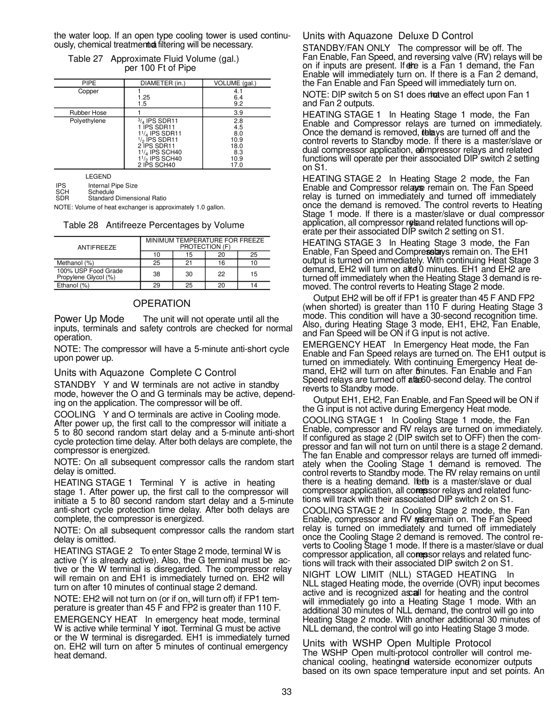
Table 27 — Approximate Fluid Volume (gal.)
per 100 Ft of Pipe
| PIPE | | DIAMETER (in.) | VOLUME (gal.) |
| Copper | | 1 | 4.1 |
| | | 1.25 | 6.4 |
| | | 1.5 | 9.2 |
| Rubber Hose | | 1 | 3.9 |
| Polyethylene | | 3/4 IPS SDR11 | 2.8 |
| | | 1 IPS SDR11 | 4.5 |
| | | 11/4 IPS SDR11 | 8.0 |
| | | 1/2 IPS SDR11 | 10.9 |
| | | 2 IPS SDR11 | 18.0 |
| | | 11/4 IPS SCH40 | 8.3 |
| | | 11/2 IPS SCH40 | 10.9 |
| | | 2 IPS SCH40 | 17.0 |
| LEGEND | | |
IPS | — Internal Pipe Size | | |
SCH | — Schedule | | |
SDR | — Standard Dimensional Ratio | |
NOTE: Volume of heat exchanger is approximately 1.0 gallon.
Table 28 — Antifreeze Percentages by Volume
| | MINIMUM TEMPERATURE FOR FREEZE |
| ANTIFREEZE | | PROTECTION (F) | |
| | 10 | 15 | 20 | 25 |
| Methanol (%) | 25 | 21 | 16 | 10 |
| 100% USP Food Grade | 38 | 30 | 22 | 15 |
| Propylene Glycol (%) |
| | | | |
| Ethanol (%) | 29 | 25 | 20 | 14 |
OPERATION
Power Up Mode — The unit will not operate until all the inputs, terminals and safety controls are checked for normal operation.
NOTE: The compressor will have a 5-minute anti-short cycle upon power up.
Units with Aquazone™ Complete C Control
STANDBY — Y and W terminals are not active in standby mode, however the O and G terminals may be active, depend- ing on the application. The compressor will be off.
COOLING — Y and O terminals are active in Cooling mode. After power up, the first call to the compressor will initiate a 5 to 80 second random start delay and a 5-minute anti-short cycle protection time delay. After both delays are complete, the compressor is energized.
NOTE: On all subsequent compressor calls the random start delay is omitted.
HEATING STAGE 1 — Terminal Y is active in heating stage 1. After power up, the first call to the compressor will initiate a 5 to 80 second random start delay and a 5-minute anti-short cycle protection time delay. After both delays are complete, the compressor is energized.
NOTE: On all subsequent compressor calls the random start delay is omitted.
HEATING STAGE 2 — To enter Stage 2 mode, terminal W is active (Y is already active). Also, the G terminal must be ac- tive or the W terminal is disregarded. The compressor relay will remain on and EH1 is immediately turned on. EH2 will turn on after 10 minutes of continual stage 2 demand.
NOTE: EH2 will not turn on (or if on, will turn off) if FP1 tem- perature is greater than 45 F and FP2 is greater than 110 F.
EMERGENCY HEAT — In emergency heat mode, terminal W is active while terminal Y is not. Terminal G must be active or the W terminal is disregarded. EH1 is immediately turned on. EH2 will turn on after 5 minutes of continual emergency heat demand.
Units with Aquazone™ Deluxe D Control
STANDBY/FAN ONLY — The compressor will be off. The Fan Enable, Fan Speed, and reversing valve (RV) relays will be on if inputs are present. If there is a Fan 1 demand, the Fan Enable will immediately turn on. If there is a Fan 2 demand, the Fan Enable and Fan Speed will immediately turn on.
NOTE: DIP switch 5 on S1 does not have an effect upon Fan 1 and Fan 2 outputs.
HEATING STAGE 1 — In Heating Stage 1 mode, the Fan Enable and Compressor relays are turned on immediately. Once the demand is removed, the relays are turned off and the control reverts to Standby mode. If there is a master/slave or dual compressor application, all compressor relays and related functions will operate per their associated DIP switch 2 setting on S1.
HEATING STAGE 2 — In Heating Stage 2 mode, the Fan Enable and Compressor relays are remain on. The Fan Speed relay is turned on immediately and turned off immediately once the demand is removed. The control reverts to Heating Stage 1 mode. If there is a master/slave or dual compressor application, all compressor relays and related functions will op- erate per their associated DIP switch 2 setting on S1.
HEATING STAGE 3 — In Heating Stage 3 mode, the Fan Enable, Fan Speed and Compressor relays remain on. The EH1 output is turned on immediately. With continuing Heat Stage 3 demand, EH2 will turn on after 10 minutes. EH1 and EH2 are turned off immediately when the Heating Stage 3 demand is re- moved. The control reverts to Heating Stage 2 mode.
Output EH2 will be off if FP1 is greater than 45 F AND FP2 (when shorted) is greater than 110 F during Heating Stage 3 mode. This condition will have a 30-second recognition time. Also, during Heating Stage 3 mode, EH1, EH2, Fan Enable, and Fan Speed will be ON if G input is not active.
EMERGENCY HEAT — In Emergency Heat mode, the Fan Enable and Fan Speed relays are turned on. The EH1 output is turned on immediately. With continuing Emergency Heat de- mand, EH2 will turn on after 5 minutes. Fan Enable and Fan Speed relays are turned off after a 60-second delay. The control reverts to Standby mode.
Output EH1, EH2, Fan Enable, and Fan Speed will be ON if the G input is not active during Emergency Heat mode. COOLING STAGE 1 — In Cooling Stage 1 mode, the Fan Enable, compressor and RV relays are turned on immediately. If configured as stage 2 (DIP switch set to OFF) then the com- pressor and fan will not turn on until there is a stage 2 demand. The fan Enable and compressor relays are turned off immedi- ately when the Cooling Stage 1 demand is removed. The control reverts to Standby mode. The RV relay remains on until there is a heating demand. If there is a master/slave or dual compressor application, all compressor relays and related func- tions will track with their associated DIP switch 2 on S1. COOLING STAGE 2 — In Cooling Stage 2 mode, the Fan Enable, compressor and RV relays remain on. The Fan Speed relay is turned on immediately and turned off immediately once the Cooling Stage 2 demand is removed. The control re- verts to Cooling Stage 1 mode. If there is a master/slave or dual compressor application, all compressor relays and related func- tions will track with their associated DIP switch 2 on S1. NIGHT LOW LIMIT (NLL) STAGED HEATING — In NLL staged Heating mode, the override (OVR) input becomes active and is recognized as a call for heating and the control will immediately go into a Heating Stage 1 mode. With an additional 30 minutes of NLL demand, the control will go into Heating Stage 2 mode. With another additional 30 minutes of NLL demand, the control will go into Heating Stage 3 mode.
Units with WSHP Open Multiple Protocol —
The WSHP Open multi-protocol controller will control me- chanical cooling, heating and waterside economizer outputs based on its own space temperature input and set points. An