Carrier 50RHE006-060 Control Accessory Relay Configurations, Start-Up, Operating Limits

Models: 50RHE006-060

1 32
Download 32 pages 52.62 Kb
Page 18
Image 18

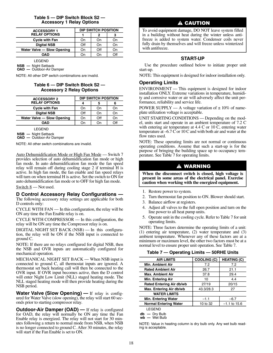
Table 5 — DIP Switch Block S2 —

Accessory 1 Relay Options

ACCESSORY 1

DIP SWITCH POSITION

RELAY OPTIONS

1

2

3

Cycle with Fan

On

On

On

Digital NSB

Off

On

On

Water Valve — Slow Opening

On

Off

On

OAD

On

On

Off

LEGEND


NSB — Night Setback

OAD — Outdoor-Air Damper

NOTE: All other DIP switch combinations are invalid.

Table 6 — DIP Switch Block S2 —

Accessory 2 Relay Options

ACCESSORY 2

DIP SWITCH POSITION

RELAY OPTIONS

4

5

6

Cycle with Fan

On

On

On

Digital NSB

Off

On

On

Water Valve — Slow Opening

On

Off

On

OAD

On

On

Off

LEGEND


NSB — Night Setback

OAD — Outdoor-Air Damper

NOTE: All other switch combinations are invalid.

Auto Dehumidification Mode or High Fan Mode — Switch 7 provides selection of auto dehumidification fan mode or high fan mode. In auto dehumidification fan mode the fan speed relay will remain off during cooling stage 2 if terminal H is active. In high fan mode, the fan enable and fan speed relays will turn on when terminal H is active. Set the switch to ON for auto dehumidification fan mode or to OFF for high fan mode.

Switch 8 — Not used.

D Control Accessory Relay Configurations —

The following accessory relay settings are applicable for both D controls only:

CYCLE WITH FAN — In this configuration, the relay will be ON any time the Fan Enable relay is on.

CYCLE WITH COMPRESSOR — In this configuration, the relay will be ON any time the Compressor relay is on.

DIGITAL NIGHT SET BACK (NSB) — In this configura- tion, the relay will be ON if the NSB input is connected to ground C.

NOTE: If there are no relays configured for digital NSB, then the NSB and OVR inputs are automatically configured for mechanical operation.

MECHANICAL NIGHT SET BACK — When NSB input is connected to ground C, all thermostat inputs are ignored. A thermostat set back heating call will then be connected to the OVR input. If OVR input becomes active, then the D control will enter Night Low Limit (NLL) staged heating mode. The NLL staged heating mode will then provide heating during the NSB period.

Water Valve (Slow Opening) — If relay is config- ured for Water Valve (slow opening), the relay will start 60 sec- onds prior to starting compressor relay.

Outdoor-Air Damper (OAD) — If relay is configured for OAD, the relay will normally be ON any time the Fan Enable relay is energized. The relay will not start for 30 min- utes following a return to normal mode from NSB, when NSB is no longer connected to ground C. After 30 minutes, the relay will start if the Fan Enable is set to ON.

To avoid equipment damage, DO NOT leave system filled in a building without heat during the winter unless anti- freeze is added to system water. Condenser coils never fully drain by themselves and will freeze unless winterized with antifreeze.

START-UP

Use the procedure outlined below to initiate proper unit start-up.

NOTE: This equipment is designed for indoor installation only.

Operating Limits

ENVIRONMENT — This equipment is designed for indoor installation ONLY. Extreme variations in temperature, humidi- ty and corrosive water or air will adversely affect the unit per- formance, reliability and service life.

POWER SUPPLY — A voltage variation of ± 10% of name- plate utilization voltage is acceptable.

UNIT STARTING CONDITIONS — Depending on the mod- el, units start and operate in an ambient temperature of 7.2 C with entering air temperature at 4.4 C or 10 C, entering water temperature at –6.7 C or 10 C and with both air and water at the flow rates used.

NOTE: These operating limits are not normal or continuous operating conditions. Assume that such a start-up is for the purpose of bringing the building space up to occupancy tem- perature. See Table 7 for operating limits.

When the disconnect switch is closed, high voltage is present in some areas of the electrical panel. Exercise caution when working with the energized equipment.

1.Restore power to system.

2.Turn thermostat fan position to ON. Blower should start.

3.Balance airflow at registers.

4.Adjust all valves to the full open position and turn on the line power to all heat pump units.

5.Operate unit in the cooling cycle. Refer to Table 7 for unit operating limits.

NOTE: Three factors determine the operating limits of a unit:

(1)entering air temperature, (2) water temperature and (3) ambient temperature. Whenever any of these factors are at a minimum or maximum level, the other two factors must be at a normal level to ensure proper unit operation. See Table 7.

Table 7 — Operating Limits — 50RHE Units

AIR LIMITS

COOLING (C)

HEATING (C)

Min. Ambient Air

7.2

7.2

Rated Ambient Air

26.7

21.1

Max. Ambient Air

37.8

29.4

Min. Entering Air

10

4.4

Rated Entering Air db/wb

27/19

20/15

Max. Entering Air db/wb

43.3/28.3

27

WATER LIMITS


Min. Entering Water

–1.1

–6.7

Normal Entering Water

10 to 32

–1.1 to 15.6

LEGEND


db — Dry Bulb wb — Wet Bulb

NOTE: Value in heating column is dry bulb only. Any wet bulb read- ing is acceptable.

18

Page 18
Image 18
Carrier 50RHE006-060 specifications Control Accessory Relay Configurations, Start-Up, Operating Limits

50RHE006-060 specifications

The Carrier 50RHE006-060 is a robust commercial rooftop unit designed for efficient heating and cooling in various applications. This model is part of Carrier’s renowned line of HVAC systems, known for their reliability and performance. With a nominal cooling capacity of 5 tons and heating capacity of 6 tons, this unit is suitable for medium-sized commercial spaces such as retail stores, offices, and schools.

One of the standout features of the Carrier 50RHE006-060 is its advanced scroll compressor technology. This type of compressor is recognized for its efficiency and durability, offering quiet operation while minimizing energy consumption. The inclusion of a variable-speed blower motor enhances comfort by providing consistent airflow while also reducing energy costs by adjusting the speed according to the demand.

Another key characteristic is its integrated microprocessor control system, which allows for precise temperature management. This feature not only provides optimal comfort but also ensures energy savings. The system’s controls can be easily integrated with existing building management systems, allowing for seamless operation and monitoring.

The Carrier 50RHE006-060 boasts enhanced insulation properties, which help reduce noise during operation and improve energy efficiency. Its robust design can withstand various weather conditions, making it a reliable choice for rooftop installation. Moreover, it is designed with accessibility in mind, featuring service doors that allow for easy maintenance, reducing downtime and operational costs.

In terms of efficiency, the unit is designed to meet or exceed EPA energy efficiency standards. It utilizes environmentally friendly refrigerants, adhering to regulations aimed at reducing greenhouse gas emissions. Additionally, the design includes a high-efficiency heat exchanger, which maximizes heat transfer and improves overall performance.

The Carrier 50RHE006-060 is also equipped with a dual-stage heat function, allowing it to provide optimal heating for varying weather conditions, ensuring comfort during the colder months. Furthermore, the unit’s design incorporates features such as hot gas bypass for improved dehumidification, making it adaptable to different climates and enhancing indoor air quality.

In summary, the Carrier 50RHE006-060 stands out with its efficient compressor technology, smart control systems, robust construction, and environmentally conscious design. These features make it a top choice for commercial spaces seeking an effective, reliable, and energy-efficient heating and cooling solution.