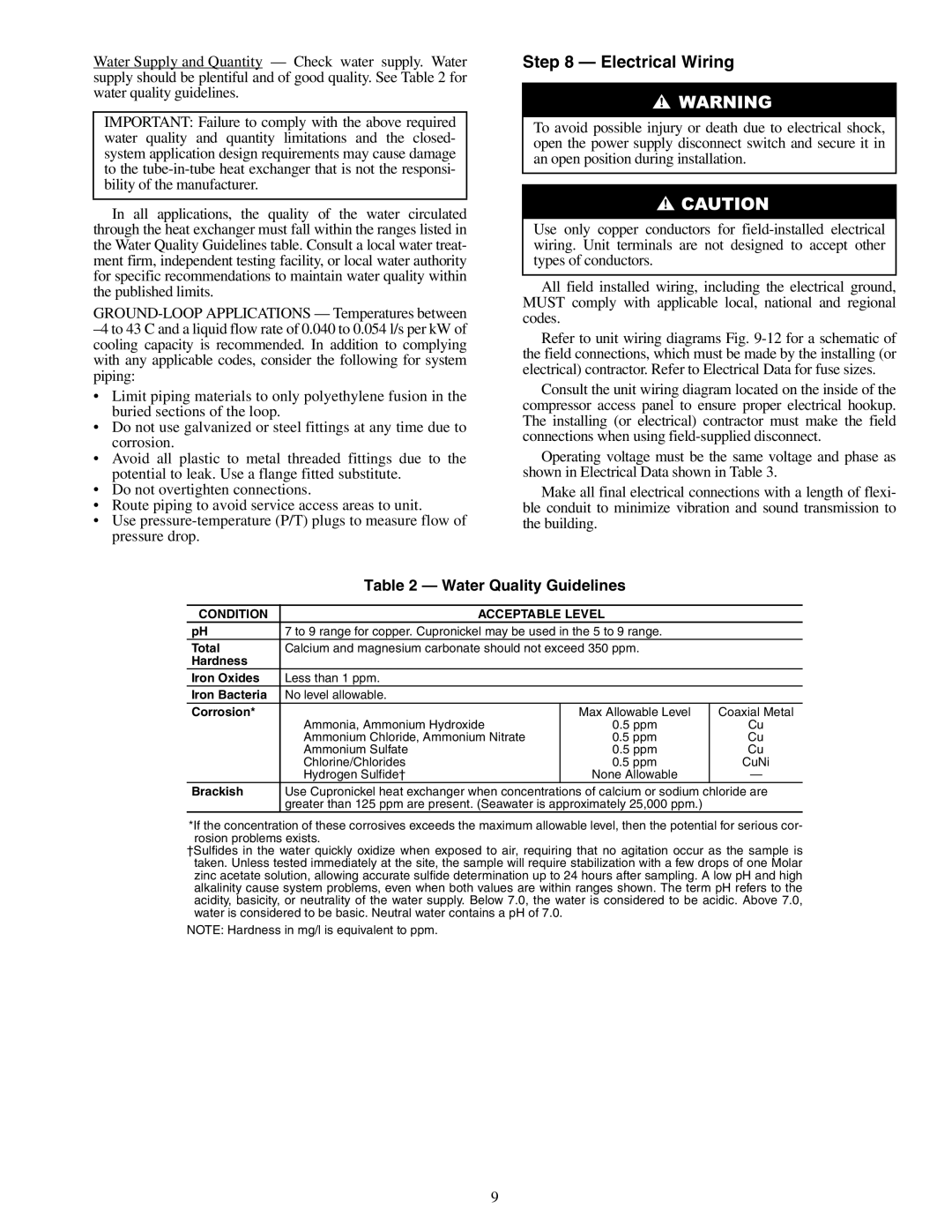
Water Supply and Quantity — Check water supply. Water supply should be plentiful and of good quality. See Table 2 for water quality guidelines.

IMPORTANT: Failure to comply with the above required water quality and quantity limitations and the closed- system application design requirements may cause damage to the tube-in-tube heat exchanger that is not the responsi- bility of the manufacturer.

In all applications, the quality of the water circulated through the heat exchanger must fall within the ranges listed in the Water Quality Guidelines table. Consult a local water treat- ment firm, independent testing facility, or local water authority for specific recommendations to maintain water quality within the published limits.

GROUND-LOOP APPLICATIONS — Temperatures between –4 to 43 C and a liquid flow rate of 0.040 to 0.054 l/s per kW of cooling capacity is recommended. In addition to complying with any applicable codes, consider the following for system piping:

Limit piping materials to only polyethylene fusion in the buried sections of the loop.

Do not use galvanized or steel fittings at any time due to corrosion.

Avoid all plastic to metal threaded fittings due to the potential to leak. Use a flange fitted substitute.

Do not overtighten connections.

Route piping to avoid service access areas to unit.

Use pressure-temperature (P/T) plugs to measure flow of pressure drop.

Step 8 — Electrical Wiring

To avoid possible injury or death due to electrical shock, open the power supply disconnect switch and secure it in an open position during installation.

Use only copper conductors for field-installed electrical wiring. Unit terminals are not designed to accept other types of conductors.

All field installed wiring, including the electrical ground, MUST comply with applicable local, national and regional codes.

Refer to unit wiring diagrams Fig. 9-12 for a schematic of the field connections, which must be made by the installing (or electrical) contractor. Refer to Electrical Data for fuse sizes.

Consult the unit wiring diagram located on the inside of the compressor access panel to ensure proper electrical hookup. The installing (or electrical) contractor must make the field connections when using field-supplied disconnect.

Operating voltage must be the same voltage and phase as shown in Electrical Data shown in Table 3.

Make all final electrical connections with a length of flexi- ble conduit to minimize vibration and sound transmission to the building.


Table 2 — Water Quality Guidelines


CONDITION

ACCEPTABLE LEVEL


pH

7 to 9 range for copper. Cupronickel may be used in the 5 to 9 range.


Total

Calcium and magnesium carbonate should not exceed 350 ppm.


Hardness


Iron Oxides

Less than 1 ppm.


Iron Bacteria

No level allowable.


Corrosion*


Max Allowable Level

Coaxial Metal


Ammonia, Ammonium Hydroxide

0.5 ppm

Cu


Ammonium Chloride, Ammonium Nitrate

0.5 ppm

Cu


Ammonium Sulfate

0.5 ppm

Cu


Chlorine/Chlorides

0.5 ppm

CuNi


Hydrogen Sulfide†

None Allowable

Brackish

Use Cupronickel heat exchanger when concentrations of calcium or sodium chloride are


greater than 125 ppm are present. (Seawater is approximately 25,000 ppm.)


*If the concentration of these corrosives exceeds the maximum allowable level, then the potential for serious cor- rosion problems exists.

†Sulfides in the water quickly oxidize when exposed to air, requiring that no agitation occur as the sample is taken. Unless tested immediately at the site, the sample will require stabilization with a few drops of one Molar zinc acetate solution, allowing accurate sulfide determination up to 24 hours after sampling. A low pH and high alkalinity cause system problems, even when both values are within ranges shown. The term pH refers to the acidity, basicity, or neutrality of the water supply. Below 7.0, the water is considered to be acidic. Above 7.0, water is considered to be basic. Neutral water contains a pH of 7.0.

NOTE: Hardness in mg/l is equivalent to ppm.

9

Page 9
Image 9
Carrier 50RHE006-060 specifications Electrical Wiring, Water Quality Guidelines, Condition Acceptable Level

50RHE006-060 specifications

The Carrier 50RHE006-060 is a robust commercial rooftop unit designed for efficient heating and cooling in various applications. This model is part of Carrier’s renowned line of HVAC systems, known for their reliability and performance. With a nominal cooling capacity of 5 tons and heating capacity of 6 tons, this unit is suitable for medium-sized commercial spaces such as retail stores, offices, and schools.

One of the standout features of the Carrier 50RHE006-060 is its advanced scroll compressor technology. This type of compressor is recognized for its efficiency and durability, offering quiet operation while minimizing energy consumption. The inclusion of a variable-speed blower motor enhances comfort by providing consistent airflow while also reducing energy costs by adjusting the speed according to the demand.

Another key characteristic is its integrated microprocessor control system, which allows for precise temperature management. This feature not only provides optimal comfort but also ensures energy savings. The system’s controls can be easily integrated with existing building management systems, allowing for seamless operation and monitoring.

The Carrier 50RHE006-060 boasts enhanced insulation properties, which help reduce noise during operation and improve energy efficiency. Its robust design can withstand various weather conditions, making it a reliable choice for rooftop installation. Moreover, it is designed with accessibility in mind, featuring service doors that allow for easy maintenance, reducing downtime and operational costs.

In terms of efficiency, the unit is designed to meet or exceed EPA energy efficiency standards. It utilizes environmentally friendly refrigerants, adhering to regulations aimed at reducing greenhouse gas emissions. Additionally, the design includes a high-efficiency heat exchanger, which maximizes heat transfer and improves overall performance.

The Carrier 50RHE006-060 is also equipped with a dual-stage heat function, allowing it to provide optimal heating for varying weather conditions, ensuring comfort during the colder months. Furthermore, the unit’s design incorporates features such as hot gas bypass for improved dehumidification, making it adaptable to different climates and enhancing indoor air quality.

In summary, the Carrier 50RHE006-060 stands out with its efficient compressor technology, smart control systems, robust construction, and environmentally conscious design. These features make it a top choice for commercial spaces seeking an effective, reliable, and energy-efficient heating and cooling solution.