TRACK

FLANGE

C08135

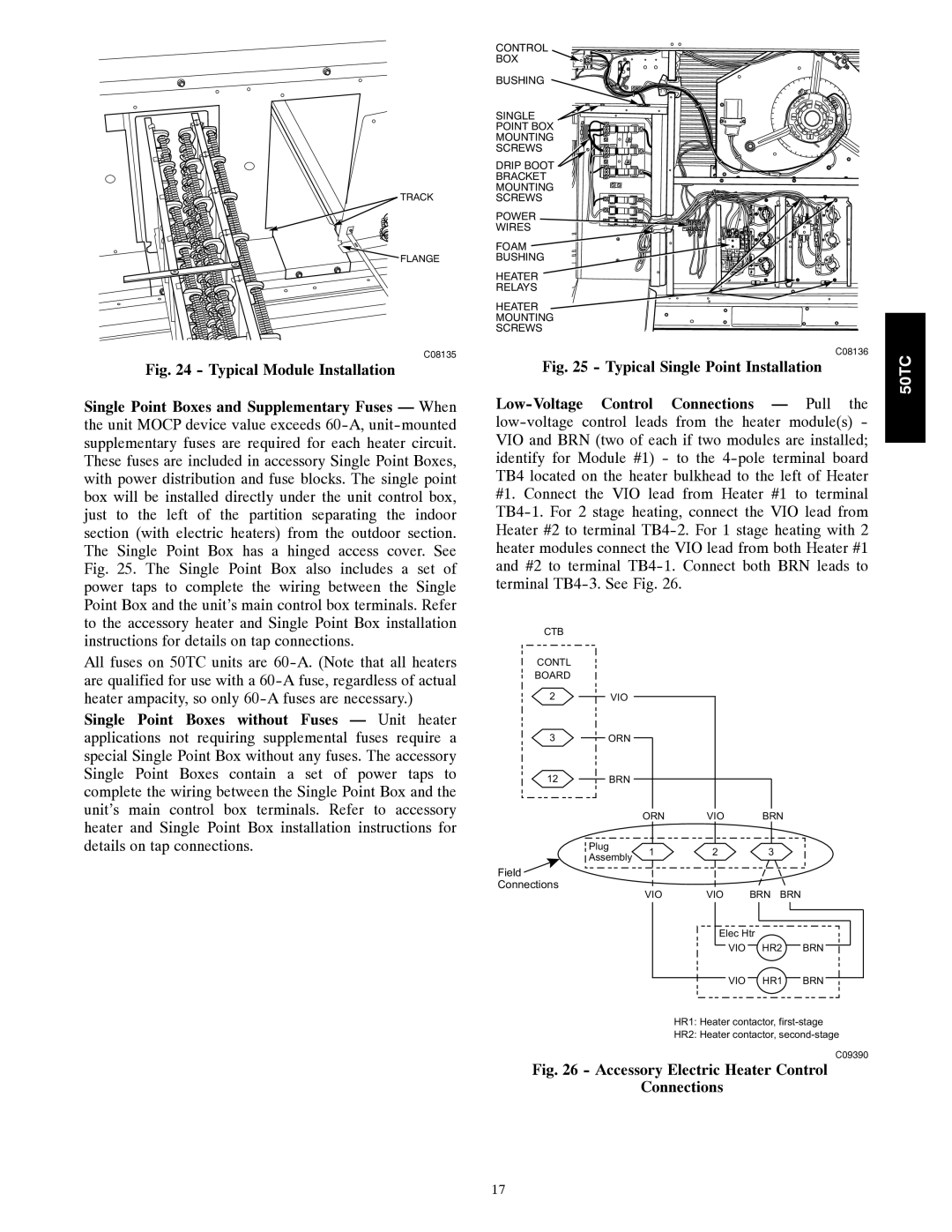
Fig. 24 - Typical Module Installation

Single Point Boxes and Supplementary Fuses — When the unit MOCP device value exceeds 60-A,unit-mounted supplementary fuses are required for each heater circuit. These fuses are included in accessory Single Point Boxes, with power distribution and fuse blocks. The single point box will be installed directly under the unit control box, just to the left of the partition separating the indoor section (with electric heaters) from the outdoor section. The Single Point Box has a hinged access cover. See Fig. 25. The Single Point Box also includes a set of power taps to complete the wiring between the Single Point Box and the unit’s main control box terminals. Refer to the accessory heater and Single Point Box installation instructions for details on tap connections.

All fuses on 50TC units are 60-A. (Note that all heaters are qualified for use with a 60-A fuse, regardless of actual heater ampacity, so only 60-A fuses are necessary.)

Single Point Boxes without Fuses — Unit heater applications not requiring supplemental fuses require a special Single Point Box without any fuses. The accessory Single Point Boxes contain a set of power taps to complete the wiring between the Single Point Box and the unit’s main control box terminals. Refer to accessory heater and Single Point Box installation instructions for details on tap connections.

CONTROL

BOX

BUSHING


SINGLE


POINT BOX


MOUNTING


SCREWS


DRIP BOOT


BRACKET


MOUNTING


SCREWS


POWER


WIRES


FOAM


BUSHING


22.2

23

1

3

HEATER

RELAYS

HEATER

MOUNTING

SCREWS

C08136

Fig. 25 - Typical Single Point Installation

Low-Voltage Control Connections — Pull the low-voltage control leads from the heater module(s) - VIO and BRN (two of each if two modules are installed; identify for Module #1) - to the 4-pole terminal board TB4 located on the heater bulkhead to the left of Heater #1. Connect the VIO lead from Heater #1 to terminal TB4-1. For 2 stage heating, connect the VIO lead from Heater #2 to terminal TB4-2. For 1 stage heating with 2 heater modules connect the VIO lead from both Heater #1 and #2 to terminal TB4-1. Connect both BRN leads to terminal TB4-3. See Fig. 26.

CTB

CONTL

BOARD

2VIO

3ORN

12 BRN


ORN

VIO

BRN


Plug

1

2

3


Assembly


Field


Connections

VIO

VIO

BRN BRN


Elec Htr


VIO

HR2

BRN


VIO

HR1

BRN


HR1: Heater contactor, first-stage


HR2: Heater contactor, second-stage

C09390

Fig. 26 - Accessory Electric Heater Control

Connections

50TC

17

Page 17
Image 17
Carrier 50TC installation instructions Accessory Electric Heater Control Connections

50TC specifications

The Carrier 50TC is a cutting-edge commercial rooftop unit designed for optimal performance and reliability in a variety of HVAC applications. This unit is particularly well-suited for small to medium-sized facilities that require efficient heating, ventilation, and air conditioning solutions. A hallmark of the Carrier 50TC is its impressive energy efficiency, enabling users to significantly lower their operational costs while maintaining a comfortable indoor environment.

One of the standout features of the Carrier 50TC is its advanced performance technologies. The unit employs a high-efficiency scroll compressor that enhances refrigerant management, allowing for exceptional cooling capacities while minimizing energy consumption. Additionally, the unit is equipped with variable speed fans, which further contribute to its operational efficiency. These fans adjust their speed according to the cooling demands, allowing the system to consume energy only when necessary.

The Carrier 50TC also incorporates an innovative control system that provides intelligent diagnostics and an array of customizable settings. This system helps in monitoring the unit's performance, ensuring maximum efficiency and early detection of potential maintenance issues. Users can easily integrate the unit within their existing building management systems, enhancing overall operational control and streamlining HVAC management procedures.

Durability and ease of maintenance are key characteristics of the Carrier 50TC, designed specifically to withstand harsh weather conditions while providing long-lasting performance. The unit's robust construction includes a powder-coated cabinet, which not only improves its aesthetic appeal but also protects against corrosion, ensuring longevity.

Moreover, the Carrier 50TC is designed with eco-friendliness in mind. It utilizes environmentally friendly refrigerants, aligning with modern regulations aimed at reducing the impact of HVAC systems on the environment. By choosing the Carrier 50TC, businesses can contribute to sustainability efforts while enjoying effective temperature control.

In summary, the Carrier 50TC combines energy efficiency, advanced technologies, and robust design to deliver a reliable HVAC solution for commercial applications. With its smart control system, high-efficiency components, and eco-friendly operation, the Carrier 50TC sets a standard for performance and sustainability in the commercial heating and cooling market.