Installation, Start-Up Service Instructions
Assembling the Roof Curb
Roof Curb 62M040 for Stand-Alone Applications
All dimensions are in inches Roof curb shipped unassembled
170-285†
Dimensions
Dimensions 075,120
Duct Sizes
62M-B-CRB-14MC 49.63 45.5
Dimensions 075,120 62M-A-CRB-14MC 30.5
Field provided
Front Rear Left Right
Required Service Clearances
Front 27.5 Rear Left Right
62MD,ME040 Outdoor Unit Dimensions
39 in. service clearance required for ERV wheel removal
62MB,MC075,120 Indoor Unit Dimensions
62MD,ME075,120 Outdoor Unit Dimensions
View A-A
55 in. service clearance required for ERV wheel removal
62MD,ME170-285 Outdoor Unit Dimensions
62 in. service clearance required for ERV wheel removal
Required Service Clearances View A-A
62MD,ME330-640 Outdoor Unit Dimensions
Front
72 in. service clearance required for ERV wheel removal
Rear Left
62MD,ME750,950 Outdoor Unit Dimensions
004-007
Rooftop
Unit Curb
Top View
Unit Curb Support
Roof Curb Location Detail
Return
48/50PG 03-07
ERV
67 3/8
TOP View
48/50HJ,TF,TJ,TM
008,009 62M-ATR-HJ78-H 62M-A-CRB-14MC
Cannot be used. Use the 62M economizer instead
Rooftop Unit Curb
Supply Return
48/50PG
62M-ATR-PG712-H
Unit Curb Rooftop Unit Curb
Side View A-A
62M-ATR-PG26-H
008,009 62M-BTR-HJ78-D 62M-B-CRB-14MC
62M-BTR-HJ36-D 62M-B-CRB-14MC
78 1 012,014 62M-BTR-HJ1012-D 62M-B-CRB-14MC
62M-BTR-HJ78-H 62M-B-CRB-14MC
62M-BTR-HJ36-H 62M-B-CRB-14MC
62M-BTR-HJ1012-H 62M-B-CRB-14MC
015,017 62M-BTR-HJ1525-D 62M-B-CRB-14S
Length is 891/16″ for 48/50TM028 units
62M-BTR-HJ1525-D 62M-B-CRB-14S
48/50HJ
62M-BTR-PG712-D 62M-A-CRB-14MC
62M-BTR-PG26-D 62M-A-CRB-14MC
62M-BTR-PG26-H 62M-B-CRB-14MC 80 5 44 11
Rooftop Unit Curb 38 3/4 49 5/8 ERV Curb
Curb Detail
Unit 38 3/4 Curb
020-028 62M-BTR-HG1525-H 62M-B-CRB-14MC 114.4 78.6
20-28 62M-BTR-HG1525-H 62M-B-CRB-14MC 114.4 78.6
48/50HJ 020-028 62M-BTR-HG1525-D 62M-B-CRB-14MC 114.4
48/50PG 20-28 62M-BTR-HG1525-D 62M-B-CRB-14MC 114.4
012,014 62M-CTR-HJ1012-D 62M-C-CRB-14M
Supply
62M-CTR-HJ1012-HEC 62M-C-CRB-14M
62M-CTR-HJ1012-H 62M-C-CRB-14M
74 1/4
Rooftop Unit Accessory
Transition Rooftop Unit Accessory 62M ERV Unit 62M330-640
Optional Economizer Hood Exhaust hood
48/50PG 08-14 62M-CTR-PG712-D 62M-C-CRB-14M 923/4 5315/16
60 11/32 ERV Curb
62M ERV Unit ERV Curb ERV Energy Recovery Ventilator
48/50HJ 020-028 62M-CTR-HG1525-H 62M-B-CRB-14M 114.4
48/50PG 20-28 62M-CTR-HG1525-H 62M-C-CRB-14M 114.4
48/50HJ 020-028 62M-CTR-HG1525-D 62M-B-CRB-14M 114.4
Hood rather than the bottom. The new
Hood will use the filters from the original
48/50PG 20-28 62M-CTR-HG1525-D 62M-C-CRB-14M 114.4
48/50A 020-060 62M-CTR-AJ2060-D 62M-C-CRB-14M
58 3/4 ERV Curb Rooftop Unit Curb 77 3/4 Outside air
Hood 62M Unit ERV Wheel ERV Curb
Rooftop Unit Economizer See Note Standard Rooftop Unit Curb
Standard factory economizer cannot be
Used when coupled with 62M750,950 units
62M ERV Unit Rooftop
ERV Wheel Hood
48/50HJ 020-028 62M-DTR-HG1525-H 62M-D-CRB-14M 114.4
48/50PG 20-28 62M-DTR-HG1525-H 62M-D-CRB-14M 114.4
48/50PG 20-28 62M-DTR-HG1525-D 62M-D-CRB-14M 114.4
62M750,950 ERV ERV Curb
Hood O/A Outdoor Air
Relief Hood
See curb Detail 77 3/4
Rooftop Unit 62M ERV Unit
86.25 Rooftop
Unit 57 9/16 Curb 95.7
Side View
Rigging Details
Physical Data
Make Electrical Connections
Electrical Data Without VAV Option
Size
ERV
Electrical Data With VAV Option
NEC FLA MCA
VFD Exhaust and Supply Power Supply PRE Disconnect
Economizer End Switch Wiring
Typical Wiring Schematic, High Voltage
MCA Minimum Circuit Amps
Energy Recovery Ventilator
Primary
Secondary
High Voltage Low Voltage
Disconnect Fiop
START-UP
62M040-120 ERV Wheel Pressure Drop
62M550,640 62M750,950
62M550-950 ERV Wheel Pressure Drop*
62M040 Supply Air Fan Performance Curves
62M075 Supply Air Fan Performance Curves
62M120 Supply Air Fan Performance Curves
2200
2800
2600
2400
62M225 Supply Air Fan Performance Curves
62M285 Supply Air Fan Performance Curves
4500 4000
3500 3000 2500
5500 5000
4500
4000
000 500
500 000
62M640 Supply Air Fan Performance Curves
62M750 Supply Air Fan Performance Curves
10000 9500
11500 11000 10500
9000 8500 8000 7500 7000 6500
Blower Motor Pulley Adjustment
Service
Installing Wheel Segments 62M170-950 Units
Series wheel
Wheel
Drive
Motor
Maintenance
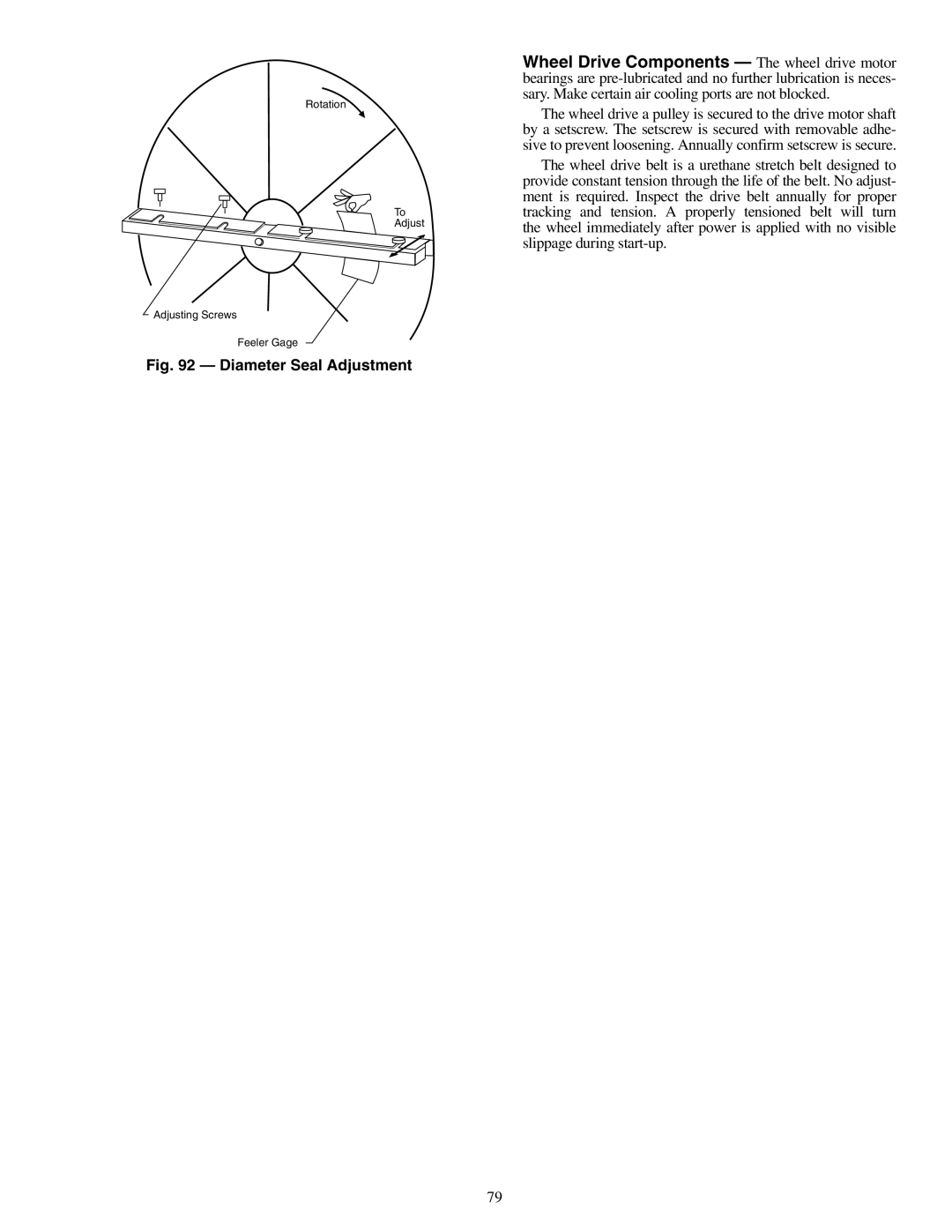
Diameter Seal Adjustment
Copyright 2006 Carrier Corporation
Page
START-UP Checklist