| See Note |
|
|
| See Note |
| See Note | See Note |
|
| |
| See Note |
|
|
| See Note |
| See Note |
|
| See Note |
|
|
| See Note |
| See Note |
|
55 |
| See Note |
|
|
See Note
See Note
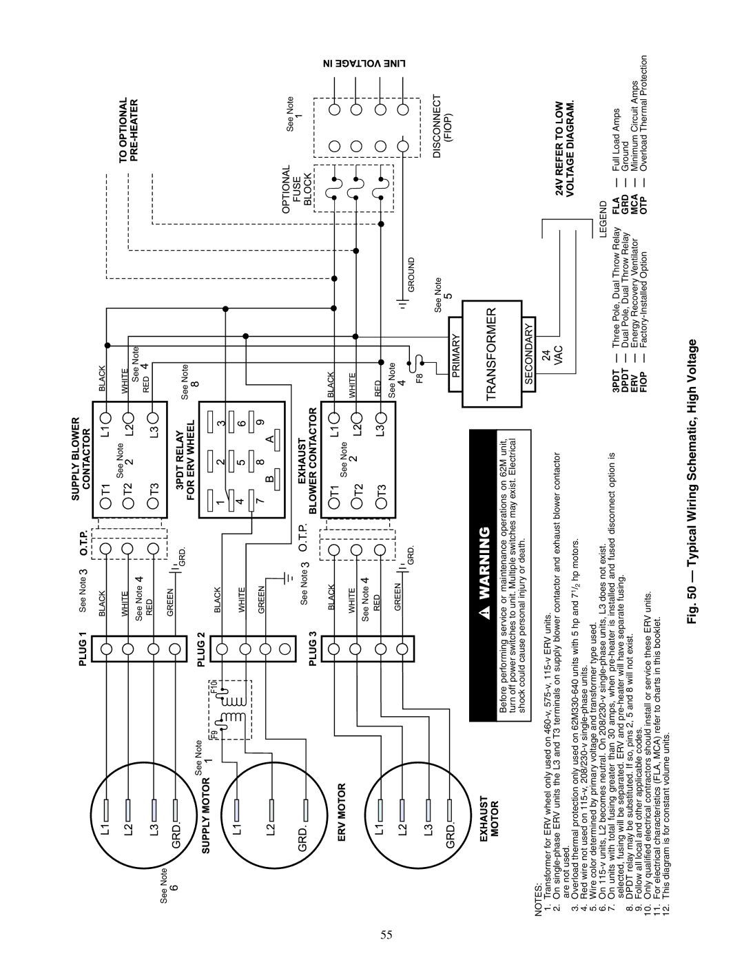
Before performing service or maintenance operations on 62M unit, turn off power switches to unit. Multiple switches may exist. Electrical shock could cause personal injury or death.
NOTES:
1.Transformer for ERV wheel only used on
2.On
3.Overload thermal protection only used on
4.Red wire not used on
5.Wire color determined by primary voltage and transformer type used.
6.On
7.On units with total fusing greater than 30 amps, when
8.DPDT relay may be substituted. If so, pins 2, 5 and 8 will not exist.
9.Follow all local and other applicable codes.
10.Only qualified electrical contractors should install or service these ERV units.
11.For electrical characteristics (FLA, MCA) refer to charts in this booklet.
12.This diagram is for constant volume units.
| LEGEND |
| |
3PDT | — Three Pole, Dual Throw Relay | FLA | — Full Load Amps |
DPDT | — Dual Pole, Dual Throw Relay | GRD — Ground | |
ERV | — Energy Recovery Ventilator | MCA — Minimum Circuit Amps | |
FIOP | — | OTP | — Overload Thermal Protection |