Removing and Installing
To remove the energy transfer wheel follow Steps
1.Pull the wheel with shaft straight out of the motor side wheel support beam and bearing. Handle wheel with care to prevent distorting of the wheel.
2.Remove the pulley side wheel support beam with bearing by removing the 4 support beam screws.
3.Remove the belt from the pulley and position temporarily around the wheel rim.
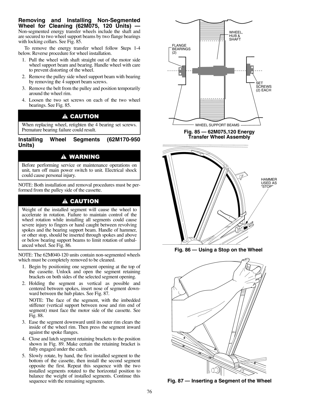
4.Loosen the two set screws on each of the two wheel bearings. See Fig. 85.
FLANGE BEARINGS
(2)
WHEEL,
HUB &
SHAFT
SET SCREWS
(2) EACH
When replacing wheel, retighten the 4 bearing set screws. Premature bearing failure could result.
Installing Wheel Segments (62M170-950 Units)
Before performing service or maintenance operations on unit, turn off main power switch to unit. Electrical shock could cause personal injury.
NOTE: Both installation and removal procedures must be per- formed from the pulley side of the cassette.
Weight of the installed segment will cause the wheel to accelerate in rotation. Failure to maintain control of the wheel rotation while installing all segments could cause severe injury to fingers or hand caught between revolving spokes and the bearing support beam. Handle of hammer, or other stop, should be inserted through spokes and above or below bearing support beams to limit rotation of unbal- anced wheel. See Fig. 86.
NOTE: The
1.Begin by positioning one segment opening at the top of the cassette. Unlock and open the segment retaining brackets on both sides of the selected segment opening.
2.Holding the segment as vertical as possible and centered between spokes, insert nose of segment down- ward between the hub plates. See Fig. 87.
NOTE: The face of the segment, with the imbedded stiffener (vertical support between nose and rim end of segment) must face the motor side of the cassette. See Fig. 88.
3.Ease the segment downward until its outer rim clears the inside of the wheel rim. Then press the segment inward against the spoke flanges.
4.Close and latch segment retaining brackets to the position shown in Fig. 89. Make certain the retaining bracket is fully engaged under the catch.
5.Slowly rotate, by hand, the first installed segment to the bottom of the cassette, then install the second segment opposite the first. Repeat this sequence with the two installed segments rotated to the horizontal position to balance the weight of installed segments. Continue this sequence with the remaining segments.
WHEEL SUPPORT BEAMS
Fig. 85 — 62M075,120 Energy
Transfer Wheel Assembly
HAMMER USED AS “STOP”
Fig. 86 — Using a Stop on the Wheel
Fig. 87 — Inserting a Segment of the Wheel
76