Imbedded Stiffeners
Fig. 88 — Motor Side View of Segment
PULL TAB
CATCH
Fig. 89— Latch Segment Retaining Brackets
Wheel Drive Motor and Pulley Replacement (62M170-095 Units)
1.Disconnect power to wheel drive motor.
2.Remove belt from pulley and position temporarily around wheel rim.
3.Loosen setscrew in wheel drive pulley using Allen wrench and remove pulley from motor drive shaft.
4.While supporting weight of drive motor in one hand, loosen and remove 4 mounting bolts.
5.Install replacement motor with hardware kit supplied.
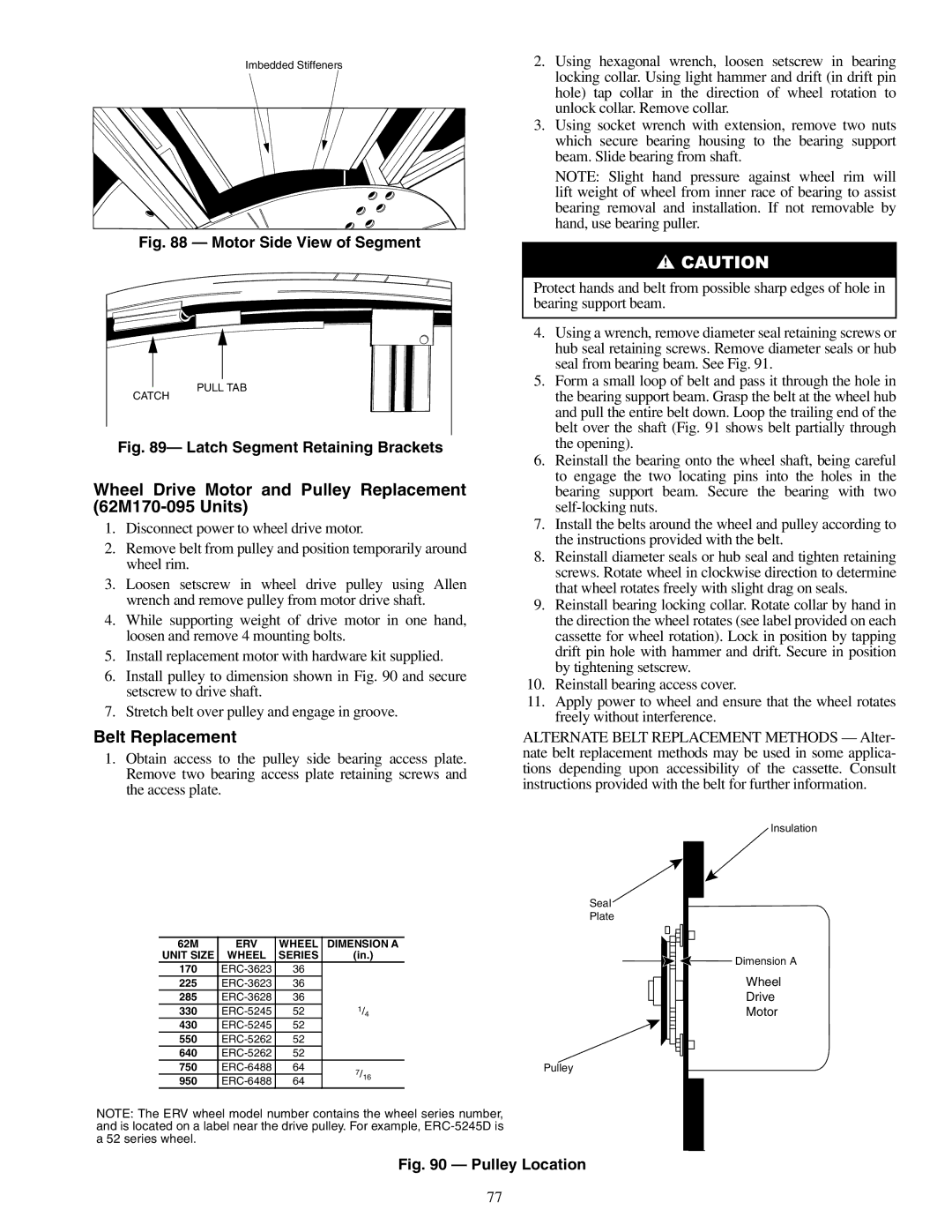
6.Install pulley to dimension shown in Fig. 90 and secure setscrew to drive shaft.
7.Stretch belt over pulley and engage in groove.
Belt Replacement
1.Obtain access to the pulley side bearing access plate. Remove two bearing access plate retaining screws and the access plate.
2.Using hexagonal wrench, loosen setscrew in bearing locking collar. Using light hammer and drift (in drift pin hole) tap collar in the direction of wheel rotation to unlock collar. Remove collar.
3.Using socket wrench with extension, remove two nuts which secure bearing housing to the bearing support beam. Slide bearing from shaft.
NOTE: Slight hand pressure against wheel rim will lift weight of wheel from inner race of bearing to assist bearing removal and installation. If not removable by hand, use bearing puller.
Protect hands and belt from possible sharp edges of hole in bearing support beam.
4.Using a wrench, remove diameter seal retaining screws or hub seal retaining screws. Remove diameter seals or hub seal from bearing beam. See Fig. 91.
5.Form a small loop of belt and pass it through the hole in the bearing support beam. Grasp the belt at the wheel hub and pull the entire belt down. Loop the trailing end of the belt over the shaft (Fig. 91 shows belt partially through the opening).
6.Reinstall the bearing onto the wheel shaft, being careful to engage the two locating pins into the holes in the bearing support beam. Secure the bearing with two
7.Install the belts around the wheel and pulley according to the instructions provided with the belt.
8.Reinstall diameter seals or hub seal and tighten retaining screws. Rotate wheel in clockwise direction to determine that wheel rotates freely with slight drag on seals.
9.Reinstall bearing locking collar. Rotate collar by hand in the direction the wheel rotates (see label provided on each cassette for wheel rotation). Lock in position by tapping drift pin hole with hammer and drift. Secure in position by tightening setscrew.
10.Reinstall bearing access cover.
11.Apply power to wheel and ensure that the wheel rotates freely without interference.
ALTERNATE BELT REPLACEMENT METHODS — Alter- nate belt replacement methods may be used in some applica- tions depending upon accessibility of the cassette. Consult instructions provided with the belt for further information.
|
|
|
| Insulation |
|
|
|
| Seal |
|
|
|
| Plate |
62M | ERV | WHEEL | DIMENSION A |
|
UNIT SIZE | WHEEL | SERIES | (in.) | Dimension A |
170 | 36 |
| ||
| Wheel | |||
225 | 36 |
| ||
285 | 36 |
| Drive | |
330 | 52 | 1/4 | Motor | |
430 | 52 |
|
| |
550 | 52 |
|
| |
640 | 52 |
|
| |
750 | 64 | 7/16 | Pulley | |
950 | 64 |
| ||
|
| |||
NOTE: The ERV wheel model number contains the wheel series number, |
| |||
and is located on a label near the drive pulley. For example, |
| |||
a 52 series wheel. |
|
|
|
|
Fig. 90 — Pulley Location
77