Return to Section TOC

Return to Section TOC

Return to Section TOC

Return to Section TOC

Return to Master TOC

Return to Master TOC

Return to Master TOC

Return to Master TOC

G-3

G-3

DIAGRAMS

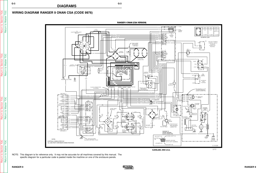
WIRING DIAGRAM RANGER 9 ONAN CSA (CODE 9976)

RANGER 9 ONAN (CSA VERSION)


254A


3 TURNS


STOP

RUN

START


4

1


L1


254


IDLER


1 & 2

4 & 6

3 & 2


(CHOKE)


S1


3


CURRENT


2


(MOMENTARY)


SENSOR


ELECTRODE POLARITY


3


SWITCH


6

12

PC


232


232


6

3

CLOSED

CLOSED

CLOSED


BOARD


224E


224E


242


242


J2

PCB1


S3 SWITCH LOGIC


240


240


236


224C


235


2C


CV-


S6


77


247


WELDING TERMINAL


CV+


S2A (CLOSED


76


250


ON


CONTROL SWITCH


75


WITH S2 IN


SHOWN IN


1

7


C1, C2 OR C3


247


"ALWAYS ON"


DC+


POSITION)


POSITION


DC-


242


5D


235


245


AM 1


4

8


AC


AMMETER


(+)

OUTPUT

100

R1


C2

C3

C4

C5


200B


+

-


208

209


254


RECTIFIER

25W


214


232A


J1


224C


D1


236A


5A


208A


216


219


31,000 MFD


201A

1

5


212


S3


236


CAPACITORS


216


(-)


236A


START


REACTOR

E


201A


RUN


208A


254A


OUTPUT


219


CONTACTOR


232


5A


240


232A


STOP


216A


S2


S1


214


216


224E


25 OHM


R2

R4

R6

C2


200B


208B


CR1


R2


3


50W


R1


R3

R5

C1

C3


3


224C


241


OUTPUT


77


RANGE


RHEOSTAT

75


250


S5


224


W2


SWITCH


MAX

10K POT


AUTO


IDLER


W1


S2


R3


75A


SWITCH


CW


5D


232A


76D


WORK

ELECTRODE


77D


5C


SHOWN IN


GND


76A


C3


"HIGH'


HIGH


POSITION


C2


S4

76


77


IDLER

L2


C1


21


SOLENOID


IN LINE CONNECTORS


6


STATOR


REMOTE SWITCH


224D


(3 PLACES)


31

42

32


3


9

7


76D


SEE DIAGRAM "A" FOR


2C


(SHOWN IN


75A


5

GND-E


REMOTE POSITION)


ENGINE TERMINAL


76A


BLOCK CONNECTION.


77A


AMPHENOL 1


77A


232A


CB1


2C


212

1


J


31A


(10AMP)


31A


3


115VAC


224B

2


OIL PRESSURE


224


A


32


GND-E


3


208

3


SWITCH


D


4A


5E


5E


GROUND SCREW


PCB2


GND-G


BLOWER BAFFLE


224A

4


CONTACTOR


5A


C


2A


BYPASS PC


GND-C


4

8


GND-D


5B


TO SPARK


WORK

H


21


5F


2A


+


REMOTE CONTROL


3E


3


PLUGS


4C


}


E


77C


CAPACITOR


-


77C


J5


+


STARTER


F


76C

76C


IGNITION


BLACK


125/250V. SINGLE


201


201A


SOLENOID


4A


COIL


G


75C

75C


RECEPTACLE


5C


AND


GREEN


-


CONTACTOR


I


31B


1

5


BLACK


8


15

BLACK


5B


216A

209


42VAC


GREEN


7


K


42


219

ENGINE


IGNITION


6

CB2


8


GND-D


15


D2


B


GND-A


115 V


9

AC

AC

(+)

(-)


HOUR METER


MODULE


GROUND


GND-G


CB4


CB6


5


75B

3

6


50A


200B


J8


15A


J6


15A


FLYWHEEL


REMOTE CONTROL


2B


115/230V

3C


3D


200A


ALTERNATOR


A


77B

77B


J4


(+)


SILVER


SLIP


B


76B

76B


BLACK


5K


(+)


12


COLORED


5L


BLACK


200


RINGS


C


75B


1


76A


11

BLACK

BLACK

TERMINALS

10


BLACK


4


GREEN


13


(+)


(-)


D


2B

4B


BLACK


10


POSITIVE SLIP


(+)


11


BLACK


13


CONTACTOR


4B


2

4

BLACK


CB5


GND-C


115 V


CB7


800 MFD


C1


RING NEAREST


VOLTAGE


E


5K


ROTOR FIELD

LAMINATION


REGULATOR

STARTER

12V


F


GND-B


3E


CB3

15A


J7


15A


201


76A


SILVER


3D


MOTOR


GROUND


50A

WHITE

3C


(-)


2C


J3

3A

COLORED


AC

B+

AC


75A


77A

3B


TERM.

3A


SILVER


WHITE


3B


B-


(-)


AMPHENOL 2


BLACK


5


DIAGRAM "A"


77A

1

3


BLACK


COLORED


5L


WHITE

BLACK


4C


BLACK


TERMINALS


ENGINE TERMINAL


WHITE


BLOCK CONNECTION


5F


GND-H


5E


208 (CAVITY #3)


224A&B (CAVITY #4)


ENGINE


LOCATING


NOTES:


GROUND SCREW


FOOT

ENGINE


TAB


CROSS


ELECTRICAL SYMBOLS PER E1537


BETWEEN AMPHENOL HOLES


WELDER LEAD END


SUPPORT


(NOTE CAVITY NUMBERS)


ALL CASE FRONT COMPONENTS VIEWED FROM REAR.


212 (CAVITY #1)


224B (CAVITY #2)


12-16-93A


CLEVELAND, OHIO U.S.A.


L9113


NOTE: This diagram is for reference only. It may not be accurate for all machines covered by this manual. The specific diagram for a particular code is pasted inside the machine on one of the enclosure panels.

RANGER 9


RANGER 9


Page 127
Image 127
Lincoln Electric SVM 110-A service manual Wiring Diagram Ranger 9 Onan CSA Code, Ranger 9 Onan CSA Version

SVM 110-A specifications

The Lincoln Electric SVM 110-A is a state-of-the-art welding machine designed to cater to the needs of professionals and hobbyists alike. Known for its adaptability and superior performance, the SVM 110-A provides a seamless welding experience that is gaining popularity across various industries.

One of the main features of the Lincoln Electric SVM 110-A is its impressive power output. Capable of delivering up to 110 amps of welding current, this machine is ideal for a wide range of applications, including light to medium fabrication work, maintenance, and repair tasks. The versatile voltage input options allow users to operate the machine on standard household current as well as generator power, enhancing its portability and usability in diverse settings.

The SVM 110-A employs advanced inverter technology, which allows for a more compact design without sacrificing performance. This technology not only improves efficiency but also provides greater control over the welding arc, ensuring cleaner beads and reduced spatter. Additionally, the inverter design contributes to a lighter weight, making the SVM 110-A easy to transport and maneuver.

Another significant characteristic of the SVM 110-A is its user-friendly interface. With intuitive controls and clear display indicators, the machine is designed for ease of use, enabling welders to quickly adjust settings to suit their specific needs. This feature is especially beneficial for beginners who are looking to enhance their skills without being overwhelmed by complex operations.

The machine supports a variety of welding processes, including MIG and stick welding, offering unmatched versatility in terms of the types of materials it can handle. From steel to aluminum, the SVM 110-A demonstrates excellent compatibility with various consumables, allowing users to select the best options for their projects.

Furthermore, the design of the SVM 110-A incorporates advanced safety features, including thermal overload protection and a sturdy construction that can withstand demanding environments. This commitment to safety ensures that users can perform their work confidently and efficiently.

In conclusion, the Lincoln Electric SVM 110-A is a remarkable welding machine that combines power, portability, and ease of use. Its advanced inverter technology, user-friendly controls, and versatility make it an ideal choice for both amateurs and seasoned welders. Whether for home projects or professional trades, the SVM 110-A stands out as a reliable and efficient solution in today’s welding landscape.