Ranger TM
Safety
California Proposition 65 Warnings
Electric Shock can kill
Cylinder may explode if damaged
Précautions DE Sûreté
Master Table of Contents for ALL Sections
Table of Contents Installation Section
Installation
Technical Specifications Ranger
Location and Ventilation
Safety Precautions
Storing
PRE-OPERATION Engine Service
Stacking
Tilting
Lifting
Muffler Relocation
Electrical Output Connections
Spark Arrester
Welding Cable Connections
Cable Length
Auxiliary Power RECEPTACLES, PLUGS, and HAND-HELD Equipment
Premises Wiring
Circuit Breakers
Figure A.2 Connection of Ranger 9 to Premises Wiring
Table of Contents Operation Section
Safety Instructions
Operation
Operating Instructions
General Description
Design Features Advantages
Operational Features and Controls
Recommended Applications
Welder
Limitations
Controls and Settings
Welding Capability
WELDER/GENERATOR Controls
Return to Section To Section TOC
Operation
Engine Operation
Gasoline Engine Controls
Before Starting the Engine
Starting the Engine
Stopping the Engine
BREAK-IN Period
Operation
Welding Operation
General Information
To Use the Ranger 9 for AC/DC TIG Constant Current Welding
Operation
Summary of Welding Processes and Machine Settings
Table B.3 Summary of Welding Processes
Auxiliary Power
Powering Motors
Table B.5 Simultaneous Welding and Auxiliary Power
Output Selector
Table B.6 Typical Generator Power Applications
Suggested Power Applications Running Watts Start-up Watts
Table of Contents Accessories
OPTIONS/ACCESSORIES
TIG Welding
Electric Shock can kill
Connection of Lincoln Electric Wire Feeders
Moving Parts can injure
Figure C.2 Ranger 9/LN-25 Across the ARC Connection Diagram
Accessories
Accessories
Accessories
Figure C.6 Ranger 9/LN-8 Connection Diagram
Connection of the LN-8 to the Ranger 9 see Figure C.6
Figure C.7 Ranger 9/LN-742 Connection Diagram
Connection of the LN-742 to the Ranger 9 see Figure C.7
115V Receptacle
Table of Contents Maintenance
Routine and Periodic Maintenance
Engine Maintenance
Figure D.1 OIL Drain and Refill Location
Figure D.2 AIR Cleaner COMPONENTS, Onan Engine
Figure D.3 SET Spark Plug GAP
Daily or Before Starting Engine
Every 25 Hours
Every 50 Hours
Every 100 Hours
Battery Maintenance
WELDER/GENERATOR Maintenance
Figure D.4 Brush Removal and Replacement
Figure D.6 Major Component Locations
Table of Contents Theory of Operation Section
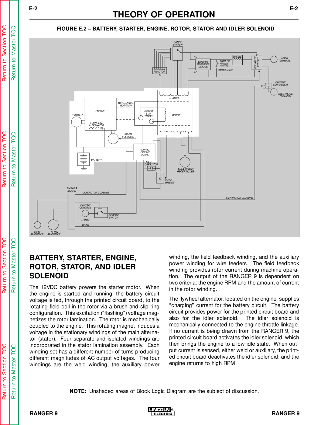
BATTERY, STARTER, ENGINE, ROTOR, STATOR, and Idler Solenoid
Theory of Operation
Rotor Field FEEDBACK, AUXILIARY, and Wire Feeder Power
Weld WINDING, REACTOR, Range Switch
Figure E.4 Weld WINDING, REACTOR, and Range Switch
Output BRIDGE, CHOKE, Polarity SWITCH, and Output Terminals
Table of Contents Troubleshooting & Repair Section
Troubleshooting & Repair
HOW to USE Troubleshooting Guide
PC Board Troubleshooting Procedures
PC Board can be damaged by static electricity
Troubleshooting Guide
Output Problems
Perform the Output Rectifier
Field Winding Voltage Test
Adjustment Test
Troubleshooting Guide
Troubleshooting & Repair
Engine Problems
Welding Terminals
Charging Circuit Test
Welding Problems
Function Problems
Perform the Auxiliary and Field
Troubleshooting & Repair
Remotely Controlled
Tor drops out, then make sure
Test Description
Rotor Voltage Test
Materials Needed
Test Procedure
Rotor Resistance Test
Rotor Resistance Test
Troubleshooting & Repair
Auxiliary and Field Winding Test
Auxiliary and Field Winding Test
To test the field winding
To test the feeder winding
Figure F.4A 14 PIN Amphenol PIN Assignments
Troubleshooting & Repair
Output Rectifier Bridge Test
Output Rectifier Bridge Test
Charging Circuit Test
Charging Circuit Test
Engine Throttle Adjustment Test
Engine Throttle Adjustment Test
Strobe-tach Method
High Idle Adjustment NUT LOW Idle Adjustment NUT
Frequency Counter Method
Oscilloscope Method Vibratach Method
Normal Open Circuit Voltage Waveform 115VAC Supply
Scope Settings
High Idle no Load Output Control AT Maximum
Machine Loaded
Typical DC Weld Output Voltage Waveform CV Mode High TAP
Machine Loaded to 250 Amps AT 25VDC
Typical DC Weld Output Voltage Waveform
Machine Loaded to 250 Amps AT 25 VDC
Typical AC Weld Output Voltage Waveform
Abnormal Open Circuit DC Weld Voltage Waveform
Abnormal Open Circuit Weld Voltage Waveform High CV Mode
Normal Open Circuit Weld Voltage Waveform High CV Mode
Normal Open Circuit DC Weld Voltage Waveform
Normal Open Circuit AC Weld Voltage Waveform
Brush Removal and Replacement
Description
Brush Removal and Replacement
Procedure
Slip Rings
Figure F.10 Brush LEADS/BRUSHES Retained with Cable TIE
Field Capacitor AND/OR Rectifier Bridge Removal Replacement
Replacement
Field Capacitor AND/OR Rectifier Bridge Removal
Procedure Rectifier Bridge Removal and Replacement
Printed Circuit Board Removal Replacement
Printed Circuit Board Removal and Replacement
Figure F.12 Printed Circuit Board Location
Printed Circuit Board Removal
Output Rectifier Bridge Removal Replacement
Remove the case top, then reinstall the fuel cap
Output Rectifier Bridge Removal
To Section TOC
Output Capacitor Removal Replacement
Output Capacitor Removal
Section TOC
Output Contactor Removal Replacement
Output Contactor Removal
Figure F.15 Output Contactor Location
Troubleshooting & REPAIRs
ENGINE/ROTOR Removal and Replacement
Instructions
ENGINE/ROTOR Removal
Figure F.17 Component LOCATIONS, ENGINE/ROTOR Removal
Engine and Rotor Removal Procedure
Rotor Removal Procedure
Figure F.18 Engine and Rotor Removed from Stator
Replacement KIT S20788
Reassembly Procedure
Retest After Repair
Table of Contents Diagrams Section
Diagrams
Wiring Diagram Ranger 9 Onan Code
Wiring Diagram Ranger 9 Onan CSA Code
Ranger 9 Onan CSA Version
Control PC Board L9062 Schematic
Snubber
RF Bypass PC Board M16675 Schematic
CLEVELAND, Ohio U
Dimension Print
Control PC Board L9062 Layout
Control PC Board L9062 Components
TP1 MOV-50VRMS,15J,14MM
Bypass
RF-BYPASS PC Board M16675 Layout
RF-BYPASS PC Board M16675 Components
Description

