Insulate Motor Terminals and Lead Wire Ends — Locate heat shrink tubing (RCD P/N LF33MM114) over power connections so that they are completely covered and tubing is against motor housing. Shrink into position. Slide foam tubing (3 in. inner diameter closed cell vinyl, neoprene, or nitrile foam) part way over the heat shrink tubing. Apply adhesive for closed cell foam insulation to motor side end of the foam tubing and push tubing the rest of the way over the terminal and against the sheet insulation on the motor side. Secure the opposite end of the foam tubing with a wire tie as shown in Fig. 28.

Alternate Insulation for Motor Terminals and Lead Wire Ends — Insulate compressor motor terminals, lead wire ends, and electrical wires to prevent moisture condensa- tion and electrical arcing. Obtain Carrier approved insula- tion material from RCD (Replacement Components Division) consisting of 3 rolls of insulation putty and one roll of vinyl tape.

a.Insulate each terminal by wrapping with one layer of insulation putty (RCD P/N 19EA411-1102).

b.Overwrap putty with 4 layers of vinyl tape.

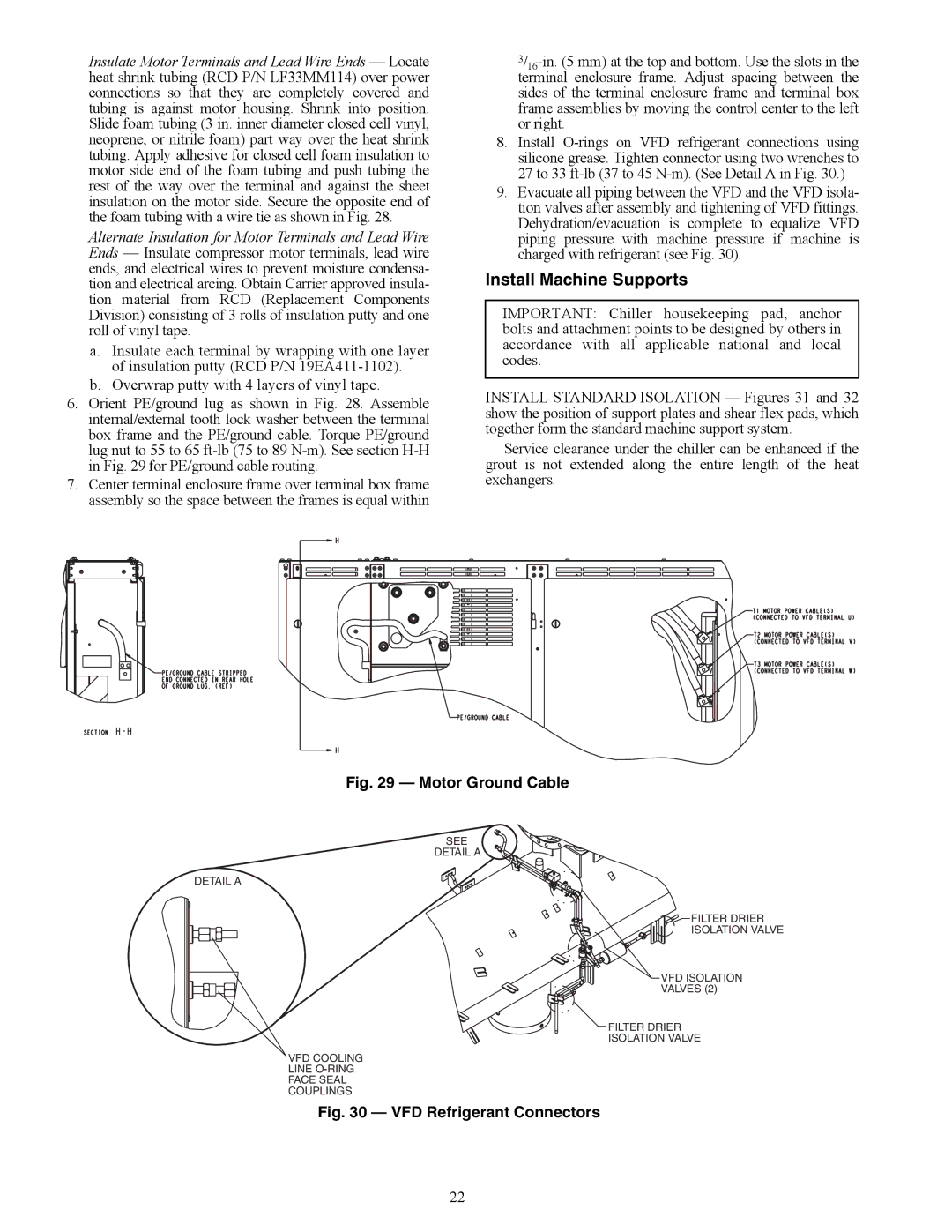
6.Orient PE/ground lug as shown in Fig. 28. Assemble internal/external tooth lock washer between the terminal box frame and the PE/ground cable. Torque PE/ground lug nut to 55 to 65 ft-lb (75 to 89 N-m). See section H-H in Fig. 29 for PE/ground cable routing.

7.Center terminal enclosure frame over terminal box frame assembly so the space between the frames is equal within

3/16-in. (5 mm) at the top and bottom. Use the slots in the terminal enclosure frame. Adjust spacing between the sides of the terminal enclosure frame and terminal box frame assemblies by moving the control center to the left or right.

8.Install O-rings on VFD refrigerant connections using silicone grease. Tighten connector using two wrenches to 27 to 33 ft-lb (37 to 45 N-m). (See Detail A in Fig. 30.)

9.Evacuate all piping between the VFD and the VFD isola- tion valves after assembly and tightening of VFD fittings. Dehydration/evacuation is complete to equalize VFD piping pressure with machine pressure if machine is charged with refrigerant (see Fig. 30).

Install Machine Supports

IMPORTANT: Chiller housekeeping pad, anchor bolts and attachment points to be designed by others in accordance with all applicable national and local codes.

INSTALL STANDARD ISOLATION — Figures 31 and 32 show the position of support plates and shear flex pads, which together form the standard machine support system.

Service clearance under the chiller can be enhanced if the grout is not extended along the entire length of the heat exchangers.

a23-1578

Fig. 29 — Motor Ground Cable

SEE

DETAIL A

DETAIL A

FILTER DRIER

ISOLATION VALVE

VFD ISOLATION

VALVES (2)

FILTER DRIER

ISOLATION VALVE

VFD COOLING

LINE O-RING

FACE SEAL

a23-1579COUPLINGS

Fig. 30 — VFD Refrigerant Connectors

22

Page 22
Image 22
Carrier HFC-134A installation instructions A23-1578, A23-1579COUPLINGS

HFC-134A specifications

Carrier HFC-134A, also known as tetrafluoroethane, is a hydrofluorocarbon (HFC) refrigerant widely used in a variety of cooling and heating applications. It is recognized for its role in refrigeration and air conditioning systems, making it a crucial component in many modern HVAC units. One of the key features of HFC-134A is its zero ozone depletion potential, which makes it an environmentally friendly alternative to older refrigerants like CFCs and HCFCs.

The characteristics of HFC-134A include its stability, non-corrosiveness, and effectiveness at low temperatures. These properties allow it to perform efficiently in both residential and commercial refrigeration systems. The refrigerant operates within a temperature range that is ideal for many applications, including food preservation and air conditioning. HFC-134A's thermodynamic properties enable it to absorb and release heat effectively, making it suitable for both vapor-compression and absorption refrigeration cycles.

From a technological perspective, the use of HFC-134A aligned with the transition to more sustainable refrigerants. As global environmental regulations have tightened, manufacturers have shifted towards refrigerants with lower global warming potential (GWP). HFC-134A has a GWP of approximately 1,430, which is lower than many of its predecessors but still higher than some newer alternatives. This aspect drives ongoing research and development in the industry, aiming to create even more environmentally sound refrigerants.

Carrier HFC-134A is compatible with various lubricants and can be integrated into systems designed for other refrigerants with minimal modifications. This flexibility allows for a smoother transition within existing installations as businesses and homeowners upgrade their HVAC systems to comply with environmental regulations.

In summary, Carrier HFC-134A plays a significant role in modern refrigeration and air conditioning technology. Its main features, including zero ozone depletion potential, stability, and efficiency, contribute to its widespread use in various applications. As the industry continues to evolve, the focus on reducing the environmental impact of refrigerants will undoubtedly influence the future direction of HFC-134A usage and the development of new alternatives.