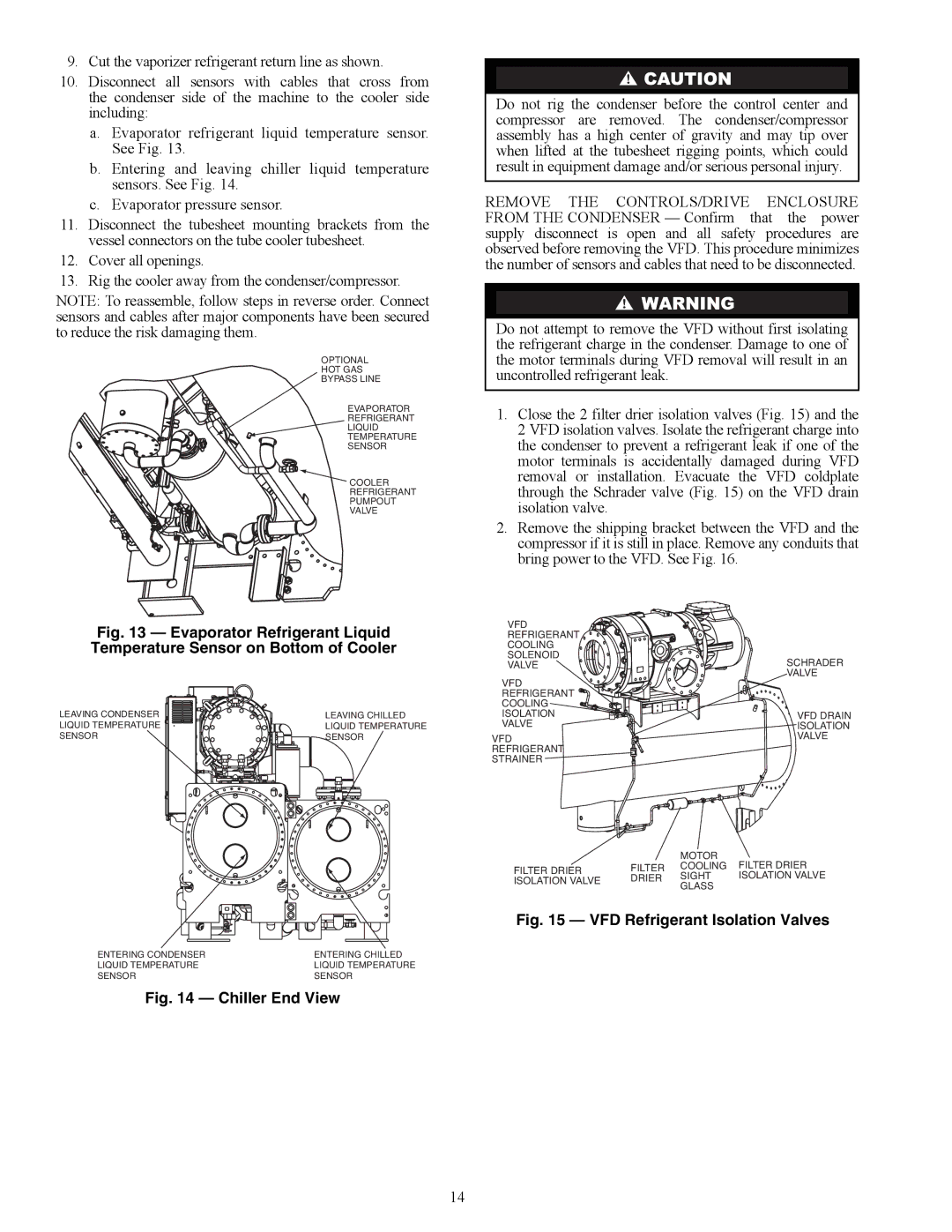
9.Cut the vaporizer refrigerant return line as shown.

10.Disconnect all sensors with cables that cross from the condenser side of the machine to the cooler side including:

a.Evaporator refrigerant liquid temperature sensor. See Fig. 13.

b.Entering and leaving chiller liquid temperature sensors. See Fig. 14.

c.Evaporator pressure sensor.

11.Disconnect the tubesheet mounting brackets from the vessel connectors on the tube cooler tubesheet.

12.Cover all openings.

13.Rig the cooler away from the condenser/compressor.

NOTE: To reassemble, follow steps in reverse order. Connect sensors and cables after major components have been secured to reduce the risk damaging them.

OPTIONAL

HOT GAS

BYPASS LINE

EVAPORATOR

REFRIGERANT

LIQUID

TEMPERATURE

SENSOR

COOLER

REFRIGERANT

PUMPOUT

VALVE

a23-1635

Fig. 13 — Evaporator Refrigerant Liquid Temperature Sensor on Bottom of Cooler

LEAVING CONDENSER

LEAVING CHILLED

LIQUID TEMPERATURE

LIQUID TEMPERATURE

SENSOR

SENSOR

ENTERING CONDENSER


ENTERING CHILLED

LIQUID TEMPERATURE

a23-1563

LIQUID TEMPERATURE

SENSOR

SENSOR


Fig. 14 — Chiller End View

Do not rig the condenser before the control center and compressor are removed. The condenser/compressor assembly has a high center of gravity and may tip over when lifted at the tubesheet rigging points, which could result in equipment damage and/or serious personal injury.

REMOVE THE CONTROLS/DRIVE ENCLOSURE FROM THE CONDENSER — Confirm that the power supply disconnect is open and all safety procedures are observed before removing the VFD. This procedure minimizes the number of sensors and cables that need to be disconnected.

Do not attempt to remove the VFD without first isolating the refrigerant charge in the condenser. Damage to one of the motor terminals during VFD removal will result in an uncontrolled refrigerant leak.

1.Close the 2 filter drier isolation valves (Fig. 15) and the 2 VFD isolation valves. Isolate the refrigerant charge into the condenser to prevent a refrigerant leak if one of the motor terminals is accidentally damaged during VFD removal or installation. Evacuate the VFD coldplate through the Schrader valve (Fig. 15) on the VFD drain isolation valve.

2.Remove the shipping bracket between the VFD and the compressor if it is still in place. Remove any conduits that bring power to the VFD. See Fig. 16.

VFD


REFRIGERANT


COOLING


SOLENOID

SCHRADER

VALVE

VFD

VALVE


REFRIGERANT


COOLING


ISOLATION

VFD DRAIN

VALVE

ISOLATION

VFD

VALVE

REFRIGERANT


STRAINER


MOTOR

FILTER DRIER

FILTER DRIER

FILTER

COOLING

SIGHT

ISOLATION VALVE

ISOLATION VALVE

DRIER

GLASS


a23-1564

Fig. 15 — VFD Refrigerant Isolation Valves

14

Page 14
Image 14
Carrier HFC-134A installation instructions A23-1635, A23-1563, A23-1564

HFC-134A specifications

Carrier HFC-134A, also known as tetrafluoroethane, is a hydrofluorocarbon (HFC) refrigerant widely used in a variety of cooling and heating applications. It is recognized for its role in refrigeration and air conditioning systems, making it a crucial component in many modern HVAC units. One of the key features of HFC-134A is its zero ozone depletion potential, which makes it an environmentally friendly alternative to older refrigerants like CFCs and HCFCs.

The characteristics of HFC-134A include its stability, non-corrosiveness, and effectiveness at low temperatures. These properties allow it to perform efficiently in both residential and commercial refrigeration systems. The refrigerant operates within a temperature range that is ideal for many applications, including food preservation and air conditioning. HFC-134A's thermodynamic properties enable it to absorb and release heat effectively, making it suitable for both vapor-compression and absorption refrigeration cycles.

From a technological perspective, the use of HFC-134A aligned with the transition to more sustainable refrigerants. As global environmental regulations have tightened, manufacturers have shifted towards refrigerants with lower global warming potential (GWP). HFC-134A has a GWP of approximately 1,430, which is lower than many of its predecessors but still higher than some newer alternatives. This aspect drives ongoing research and development in the industry, aiming to create even more environmentally sound refrigerants.

Carrier HFC-134A is compatible with various lubricants and can be integrated into systems designed for other refrigerants with minimal modifications. This flexibility allows for a smoother transition within existing installations as businesses and homeowners upgrade their HVAC systems to comply with environmental regulations.

In summary, Carrier HFC-134A plays a significant role in modern refrigeration and air conditioning technology. Its main features, including zero ozone depletion potential, stability, and efficiency, contribute to its widespread use in various applications. As the industry continues to evolve, the focus on reducing the environmental impact of refrigerants will undoubtedly influence the future direction of HFC-134A usage and the development of new alternatives.