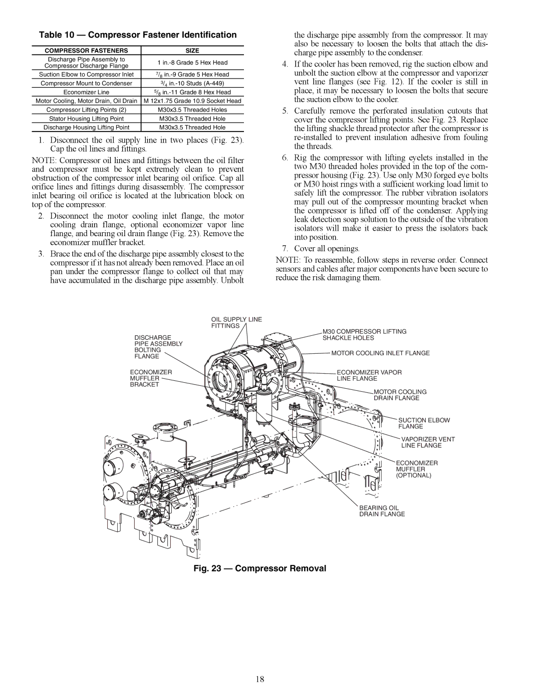
Table 10 — Compressor Fastener Identification

COMPRESSOR FASTENERS

SIZE

Discharge Pipe Assembly to

1 in.-8 Grade 5 Hex Head

Compressor Discharge Flange


Suction Elbow to Compressor Inlet

7/8 in.-9 Grade 5 Hex Head

Compressor Mount to Condenser

3/4 in.-10 Studs (A-449)

Economizer Line

5/8 in.-11 Grade 8 Hex Head

Motor Cooling, Motor Drain, Oil Drain

M 12x1.75 Grade 10.9 Socket Head

Compressor Lifting Points (2)

M30x3.5 Threaded Holes

Stator Housing Lifting Point

M30x3.5 Threaded Hole

Discharge Housing Lifting Point

M30x3.5 Threaded Hole

1.Disconnect the oil supply line in two places (Fig. 23). Cap the oil lines and fittings.

NOTE: Compressor oil lines and fittings between the oil filter and compressor must be kept extremely clean to prevent obstruction of the compressor inlet bearing oil orifice. Cap all orifice lines and fittings during disassembly. The compressor inlet bearing oil orifice is located at the lubrication block on top of the compressor.

2.Disconnect the motor cooling inlet flange, the motor cooling drain flange, optional economizer vapor line flange, and bearing oil drain flange (Fig. 23). Remove the economizer muffler bracket.

3.Brace the end of the discharge pipe assembly closest to the compressor if it has not already been removed. Place an oil pan under the compressor flange to collect oil that may have accumulated in the discharge pipe assembly. Unbolt

the discharge pipe assembly from the compressor. It may also be necessary to loosen the bolts that attach the dis- charge pipe assembly to the condenser.

4.If the cooler has been removed, rig the suction elbow and unbolt the suction elbow at the compressor and vaporizer vent line flanges (see Fig. 12). If the cooler is still in place, it may be necessary to loosen the bolts that secure the suction elbow to the cooler.

5.Carefully remove the perforated insulation cutouts that cover the compressor lifting points. See Fig. 23. Replace the lifting shackle thread protector after the compressor is re-installed to prevent insulation adhesive from fouling the threads.

6.Rig the compressor with lifting eyelets installed in the two M30 threaded holes provided in the top of the com- pressor housing (Fig. 23). Use only M30 forged eye bolts or M30 hoist rings with a sufficient working load limit to safely lift the compressor. The rubber vibration isolators may pull out of the compressor mounting bracket when the compressor is lifted off of the condenser. Applying leak detection soap solution to the outside of the vibration isolators will make it easier to press the isolators back into position.

7.Cover all openings.

NOTE: To reassemble, follow steps in reverse order. Connect sensors and cables after major components have been secure to reduce the risk damaging them.


OIL SUPPLY LINE


FITTINGS

DISCHARGE

M30 COMPRESSOR LIFTING

SHACKLE HOLES

PIPE ASSEMBLY


BOLTING

MOTOR COOLING INLET FLANGE

FLANGE


ECONOMIZER

ECONOMIZER VAPOR

MUFFLER

LINE FLANGE

BRACKET


MOTOR COOLING

DRAIN FLANGE

SUCTION ELBOW

FLANGE

VAPORIZER VENT

LINE FLANGE

ECONOMIZER MUFFLER (OPTIONAL)

BEARING OIL

DRAIN FLANGE

a23-1572

Fig. 23 — Compressor Removal

18

Page 18
Image 18
Carrier HFC-134A installation instructions Compressor Fastener Identification, A23-1572

HFC-134A specifications

Carrier HFC-134A, also known as tetrafluoroethane, is a hydrofluorocarbon (HFC) refrigerant widely used in a variety of cooling and heating applications. It is recognized for its role in refrigeration and air conditioning systems, making it a crucial component in many modern HVAC units. One of the key features of HFC-134A is its zero ozone depletion potential, which makes it an environmentally friendly alternative to older refrigerants like CFCs and HCFCs.

The characteristics of HFC-134A include its stability, non-corrosiveness, and effectiveness at low temperatures. These properties allow it to perform efficiently in both residential and commercial refrigeration systems. The refrigerant operates within a temperature range that is ideal for many applications, including food preservation and air conditioning. HFC-134A's thermodynamic properties enable it to absorb and release heat effectively, making it suitable for both vapor-compression and absorption refrigeration cycles.

From a technological perspective, the use of HFC-134A aligned with the transition to more sustainable refrigerants. As global environmental regulations have tightened, manufacturers have shifted towards refrigerants with lower global warming potential (GWP). HFC-134A has a GWP of approximately 1,430, which is lower than many of its predecessors but still higher than some newer alternatives. This aspect drives ongoing research and development in the industry, aiming to create even more environmentally sound refrigerants.

Carrier HFC-134A is compatible with various lubricants and can be integrated into systems designed for other refrigerants with minimal modifications. This flexibility allows for a smoother transition within existing installations as businesses and homeowners upgrade their HVAC systems to comply with environmental regulations.

In summary, Carrier HFC-134A plays a significant role in modern refrigeration and air conditioning technology. Its main features, including zero ozone depletion potential, stability, and efficiency, contribute to its widespread use in various applications. As the industry continues to evolve, the focus on reducing the environmental impact of refrigerants will undoubtedly influence the future direction of HFC-134A usage and the development of new alternatives.