Installation (continued)
Adjusting the feet
The four adjustable feet (p. 14) mounted at the bottom of the projector are
(Front) |
|
|
|
|
|
|
|
|
|
|
|
|
|
|
|
| (Rear) | |||||||
|
|
|
|
|
|
|
|
|
|
|
|
|
|
|
|
|
|
|
|
|
|
|
|
|
|
|
|
|
|
|
|
|
|
|
|
|
|
|
|
|
|
|
|
|
|
|
|
|
|
|
|
|
|
|
|
|
|
|
|
|
|
|
|
|
|
|
|
|
|
|
|
|
|
|
|
|
|
|
|
|
|
|
|
|
|
|
|
|
|
|
|
|
|
|
|
|
|
|
|
|
|
|
|
|
|
|
|
|
|
|
|
|
|
|
|
|
|
|
|
|
|
|
|
|
|
|
|
|
|
|
|
|
|
|
|
|
|
|
|
|
|
|
|
|
|
|
|
|
|
|
|
|
|
|
|
|
|
|
|
|
|
|
|
|
|
|
|
|
|
|
|
|
|
|
|
|
|
|
|
|
|
|
|
|
|
|
|
|
|
|
|
|
|
|
|
|
|
|
|
|
|
|
|
|
|
|
|
|
|
|
|
|
|
|
|
|
|
|
|
|
|
|
|
|
|
|
|
|
|
|
|
|
|
|
|
|
|
|
|
|
|
|
|
|
|
|
|
|
|
|
|
|
|
|
|
|
|
|
|
|
|
|
|
|
|
|
|
|
|
|
|
|
|
|
|
|
|
|
|
|
|
|
|
|
|
|
|
|
|
|
|
|
|
|
|
|
|
|
|
|
|
|
|
|
|
|
|
|
|
|
|
|
|
|
|
|
|
|
|
|
|
|
|
|
Projection scheme
All four combinations of Front, Rear, Ceiling or Floor mounting are available. Use the INSTALLATION menu to choose the desired projection scheme. (p. 78)
Installation geometry
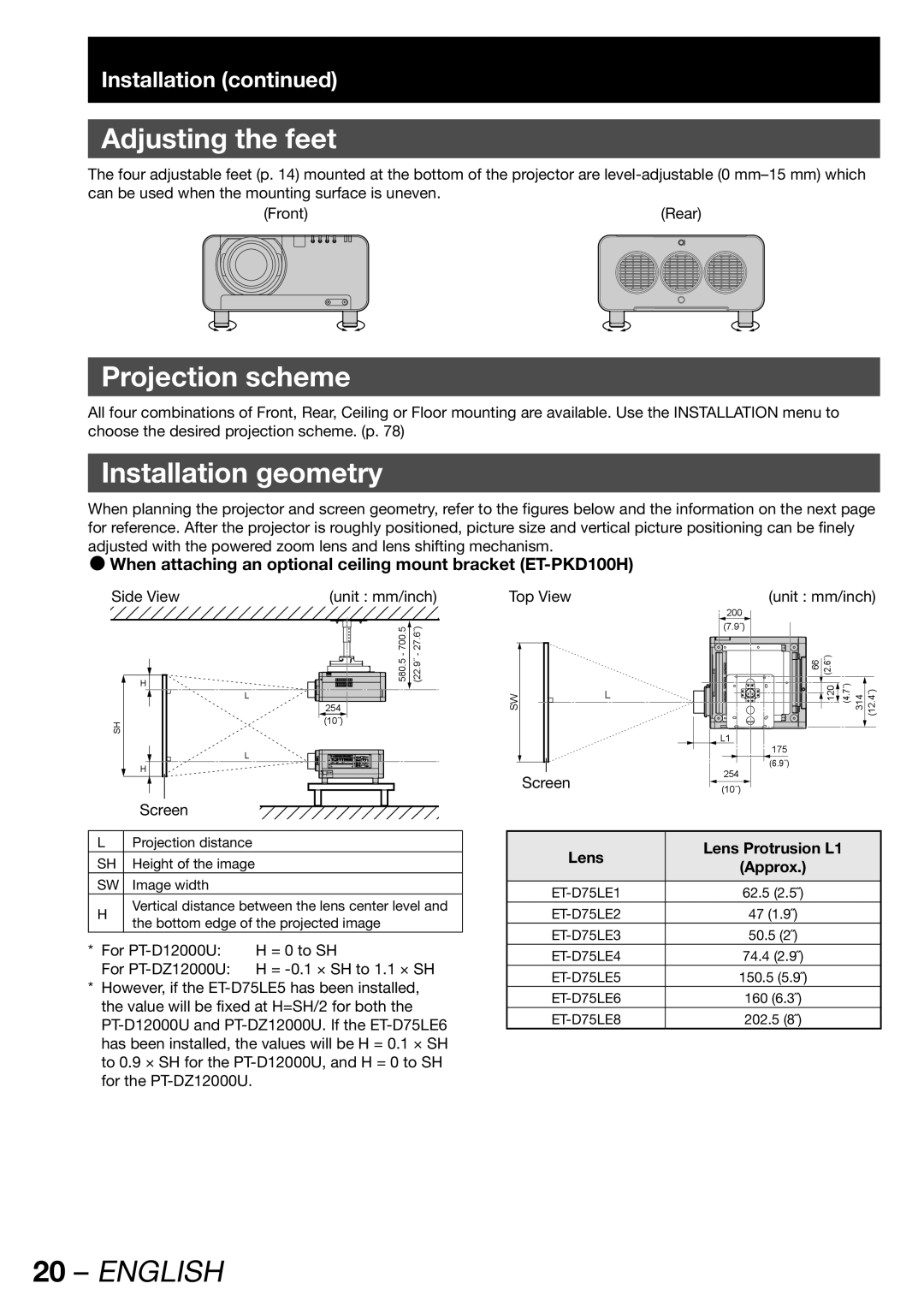
When planning the projector and screen geometry, refer to the figures below and the information on the next page for reference. After the projector is roughly positioned, picture size and vertical picture positioning can be finely adjusted with the powered zoom lens and lens shifting mechanism.
zWhen attaching an optional ceiling mount bracket (ET-PKD100H)
Side View | (unit : mm/inch) | |
| 700.5 | 27.6˝) |
H | 580.5 - | (22.9˝ - |
|
| |
| L |
|
| 254 |
|
SH | (10˝) |
|
|
| |
| L |
|
H |
|
|
Screen |
|
|
Top View | (unit : mm/inch) | ||
| 200 |
|
|
| (7.9˝) |
|
|
| 66 | (2.6˝) |
|
SW | L | 120 | (4.7˝) 314 (12.4˝) |
| |||
| L1 |
|
|
| 175 |
|
|
| (6.9˝) |
|
|
Screen | 254 |
|
|
(10˝) |
|
| |
|
|
| |
LProjection distance
SH | Height of the image |
| |
SW | Image width |
| |
H | Vertical distance between the lens center level and | ||
the bottom edge of the projected image | |||
| |||
* For | H = 0 to SH | ||
For | H = | ||
*However, if the
Lens | Lens Protrusion L1 | |
(Approx.) | ||
| ||
|
| |
62.5 (2.5˝) | ||
47 (1.9˝) | ||
50.5 (2˝) | ||
74.4 (2.9˝) | ||
150.5 (5.9˝) | ||
160 (6.3˝) | ||
202.5 (8˝) |