Installation (continued)
Calculation formulas for projection distance by lens types (for
Model number of
projection lens
|
|
|
|
| |
Zoom lens |
| |
| ||
|
| |
|
| |
|
| |
Fixed- focus | lens | |
|
| |
|
|
|
Throw ratio | Aspect ratio | Projection distance (L) formula (Units: m) | |
| 4:3 | Minimal distance : L = 0.0307 × Screen diagonal (inch) – 0.0760 | |
| Maximal distance: L = 0.0410 × Screen diagonal (inch) – 0.1004 | ||
|
| ||
16:9 | Minimal distance : L = 0.0334 × Screen diagonal (inch) – 0.0760 | ||
| |||
| Maximal distance: L = 0.0446 × Screen diagonal (inch) – 0.1004 | ||
|
| ||
| 4:3 | Minimal distance : L = 0.0412 × Screen diagonal (inch) – 0.0795 | |
| Maximal distance: L = 0.0617 × Screen diagonal (inch) – 0.1064 | ||
|
| ||
16:9 | Minimal distance : L = 0.0448 × Screen diagonal (inch) – 0.0795 | ||
| |||
| Maximal distance: L = 0.0672 × Screen diagonal (inch) – 0.1064 | ||
|
| ||
| 4:3 | Minimal distance : L = 0.0617 × Screen diagonal (inch) – 0.0958 | |
| Maximal distance: L = 0.1031 × Screen diagonal (inch) – 0.1216 | ||
|
| ||
16:9 | Minimal distance : L = 0.0672 × Screen diagonal (inch) – 0.0958 | ||
| |||
| Maximal distance: L = 0.1123 × Screen diagonal (inch) – 0.1216 | ||
|
| ||
| 4:3 | Minimal distance : L = 0.1031 × Screen diagonal (inch) – 0.1158 | |
| Maximal distance: L = 0.1639 × Screen diagonal (inch) – 0.1013 | ||
|
| ||
16:9 | Minimal distance : L = 0.1123 × Screen diagonal (inch) – 0.1158 | ||
| |||
| Maximal distance: L = 0.1786 × Screen diagonal (inch) – 0.1013 | ||
|
| ||
4:3 | Minimal distance : L = 0.1640 × Screen diagonal (inch) – 0.3862 | ||
Maximal distance: L = 0.3072 × Screen diagonal (inch) – 0.3598 | |||
|
| ||
| 16:9 | Minimal distance : L = 0.1786 × Screen diagonal (inch) – 0.3862 | |
Maximal distance: L = 0.3346 × Screen diagonal (inch) – 0.3598 | |||
|
| ||
| 4:3 | Minimal distance : L = 0.0207 × Screen diagonal (inch) – 0.0566 | |
| Maximal distance: L = 0.0248 × Screen diagonal (inch) – 0.0736 | ||
|
| ||
16:9 | Minimal distance : L = 0.0225 × Screen diagonal (inch) – 0.0566 | ||
| |||
| Maximal distance: L = 0.0270 × Screen diagonal (inch) – 0.0736 | ||
|
| ||
0.8 : 1 | 4:3 | L = 0.0158 × Screen diagonal (inch) – 0.0835 | |
|
| ||
16:9 | L = 0.0172 × Screen diagonal (inch) – 0.0835 | ||
| |||
|
|
|
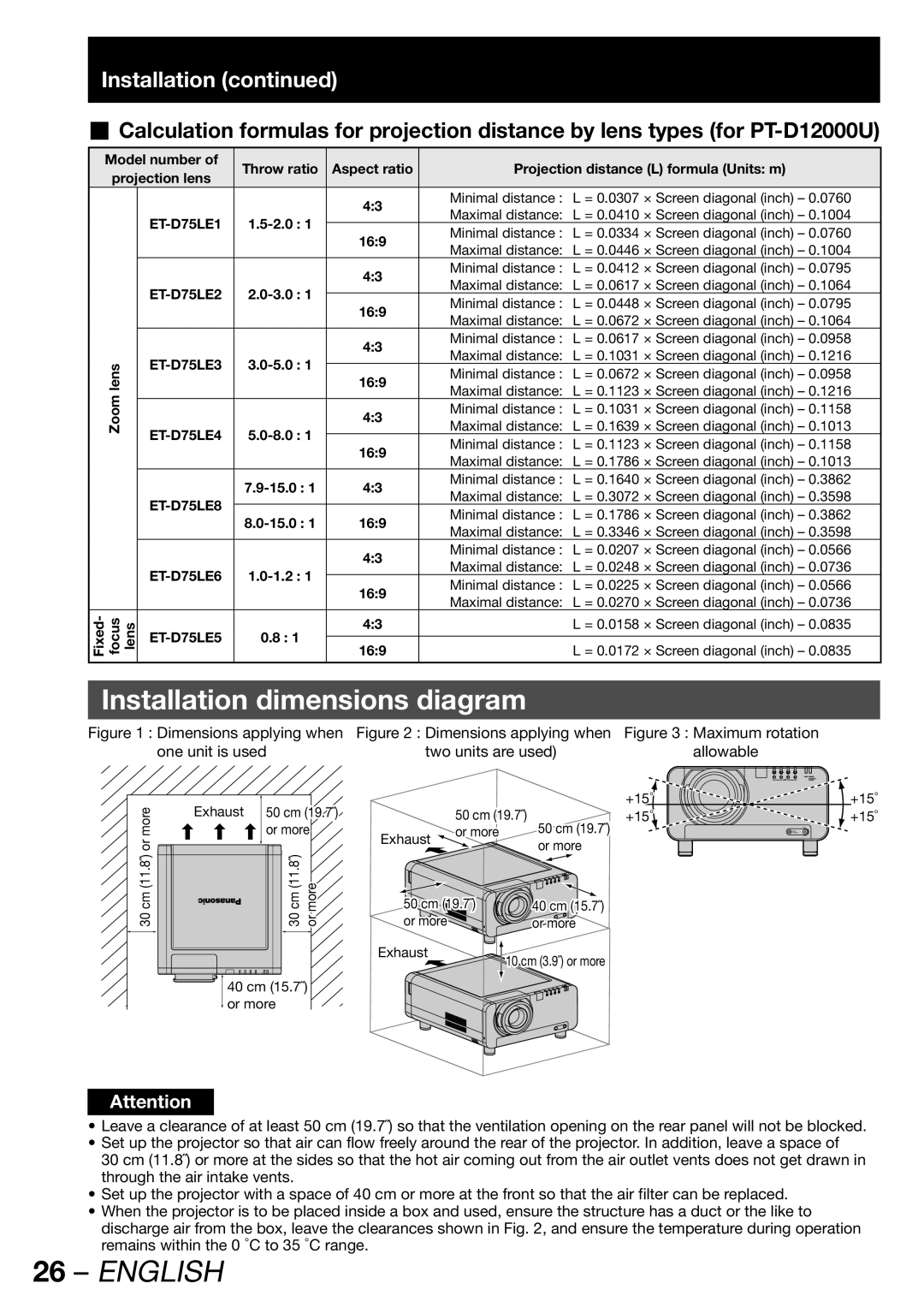
Installation dimensions diagram
Figure 1 : Dimensions applying when | Figure 2 : Dimensions applying when | Figure 3 : Maximum rotation | |||||||||||||||
one unit is used | two units are used) |
|
| allowable | |||||||||||||
|
|
|
|
|
|
|
|
|
|
|
|
|
|
|
|
|
|
|
|
|
|
|
|
|
|
|
|
|
|
|
|
|
|
|
|
more | Exhaust | 50 cm (19.7˝) |
|
| +15° | +15° | |
| 50 cm (19.7˝) | +15° | +15° | ||||
| or more | Exhaust | or more | 50 cm (19.7˝) |
| ||
or |
|
|
|
| or more |
| |
|
|
|
|
|
| ||
cm (11.8˝) |
| cm (11.8˝) | more | 50 cm (19.7˝) | 40 cm (15.7˝) |
| |
30 |
| 30 | or | or more |
| or more |
|
|
|
|
| Exhaust | 10 cm (3.9˝) or more |
| |
|
|
|
|
|
| ||
| 40 cm (15.7˝) |
|
|
|
| ||
| or more |
|
|
|
|
| |
Attention
•Leave a clearance of at least 50 cm (19.7˝) so that the ventilation opening on the rear panel will not be blocked.
•Set up the projector so that air can flow freely around the rear of the projector. In addition, leave a space of
30 cm (11.8˝) or more at the sides so that the hot air coming out from the air outlet vents does not get drawn in through the air intake vents.
•Set up the projector with a space of 40 cm or more at the front so that the air filter can be replaced.
•When the projector is to be placed inside a box and used, ensure the structure has a duct or the like to discharge air from the box, leave the clearances shown in Fig. 2, and ensure the temperature during operation remains within the 0 °C to 35 °C range.