Using the Remote 2 terminal
Using the REMOTE 2 terminal provided on the connection terminals of the main unit, it is possible to operate the projector from a control panel etc. furnished in a distant location where infrared remote control signal cannot be received.
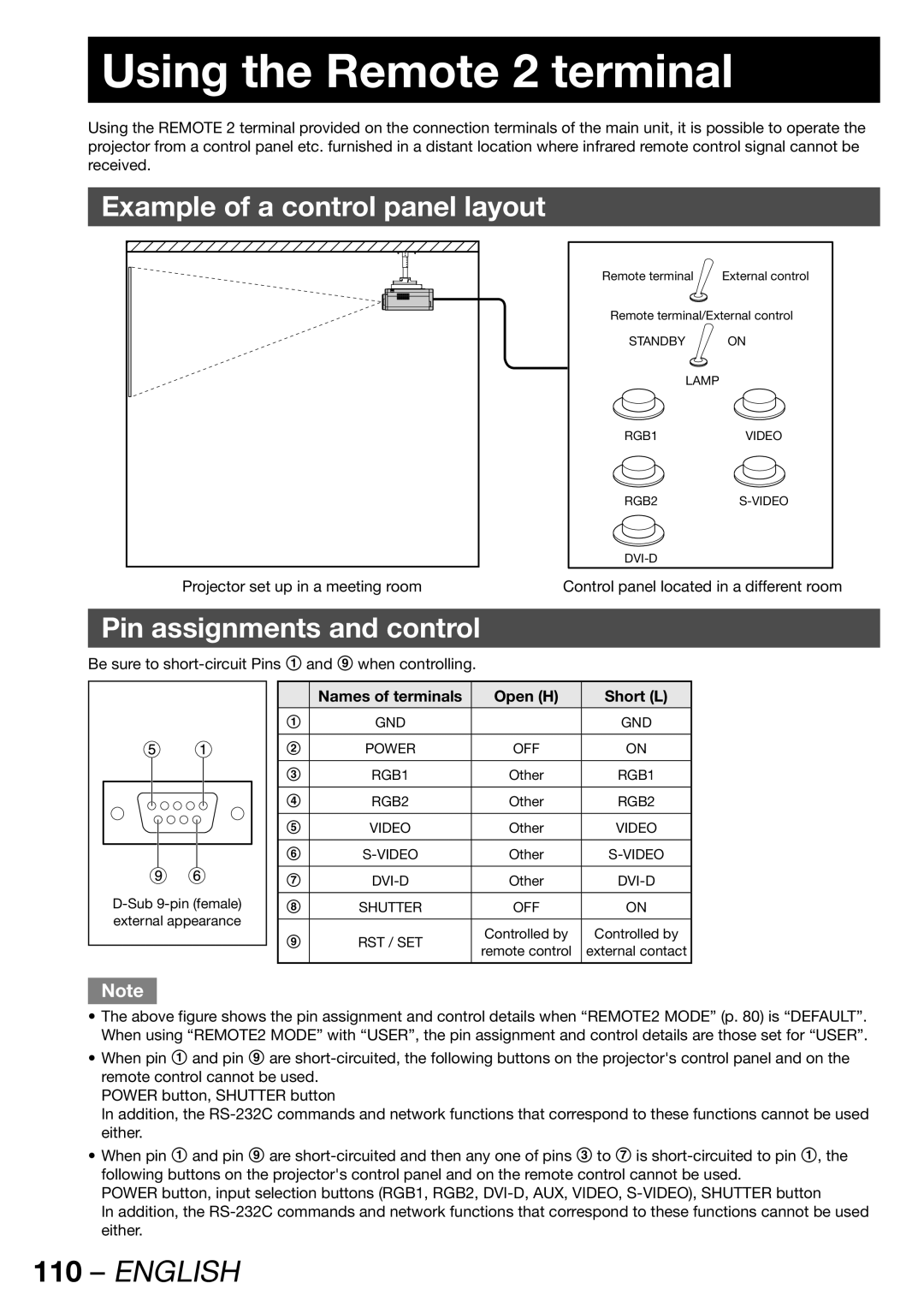
Example of a control panel layout
Remote terminal | External control |
Remote terminal/External control
STANDBY ON
LAMP
RGB1VIDEO
RGB2S-VIDEO
Projector set up in a meeting room | Control panel located in a different room |
Pin assignments and control
Be sure to
external appearance |
| Names of terminals | Open (H) | Short (L) | |
|
|
|
| |
1 | GND |
| GND | |
|
|
|
| |
2 | POWER | OFF | ON | |
|
|
|
| |
3 | RGB1 | Other | RGB1 | |
|
|
|
| |
4 | RGB2 | Other | RGB2 | |
|
|
|
| |
5 | VIDEO | Other | VIDEO | |
|
|
|
| |
6 | Other | |||
|
|
|
| |
7 | Other | |||
|
|
|
| |
8 | SHUTTER | OFF | ON | |
|
|
|
| |
9 | RST / SET | Controlled by | Controlled by | |
remote control | external contact | |||
|
| |||
|
|
|
|
Note
•The above figure shows the pin assignment and control details when “REMOTE2 MODE” (p. 80) is “DEFAULT”. When using “REMOTE2 MODE” with “USER”, the pin assignment and control details are those set for “USER”.
•When pin 1 and pin 9 are
POWER button, SHUTTER button
In addition, the
•When pin 1 and pin 9 are
POWER button, input selection buttons (RGB1, RGB2,
In addition, the