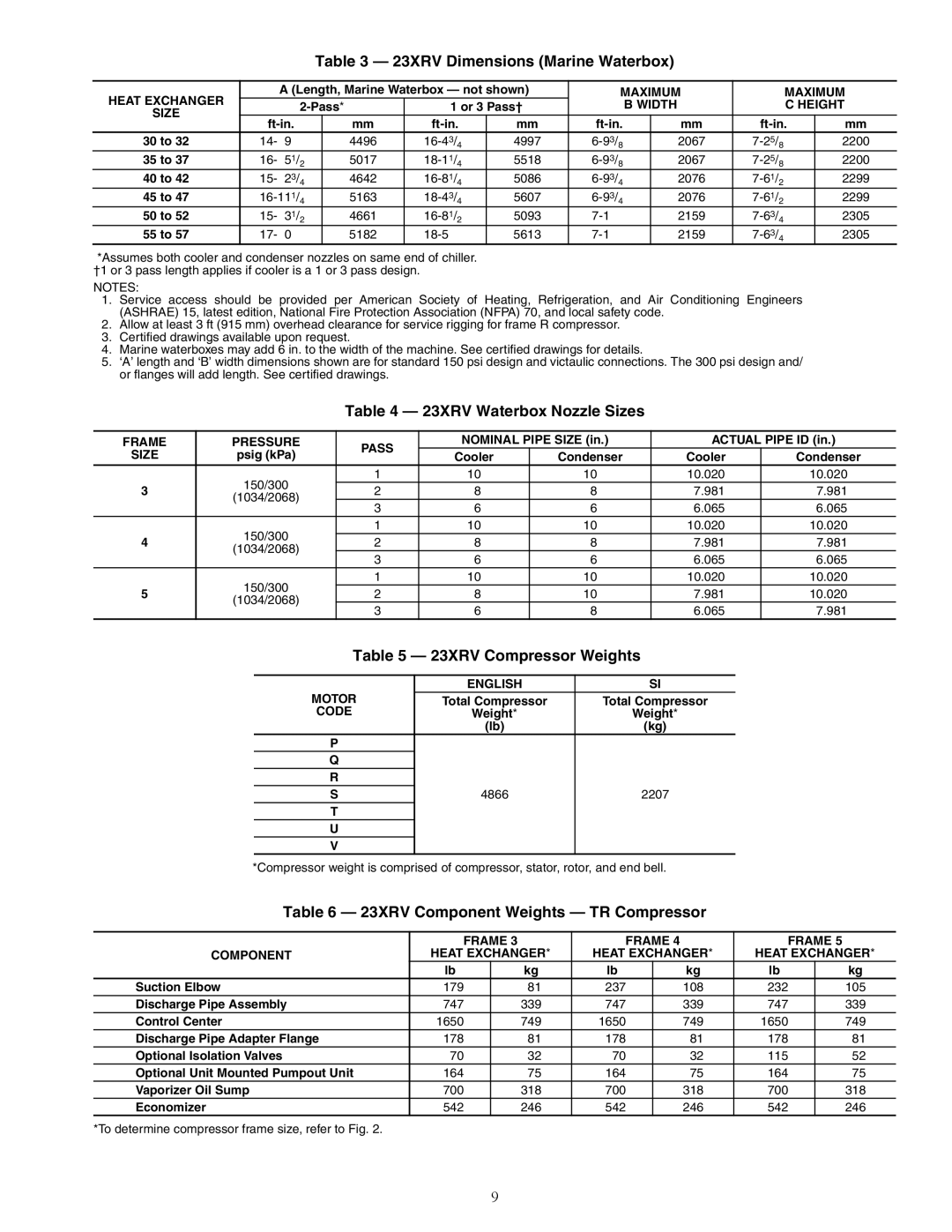
Table 3 — 23XRV Dimensions (Marine Waterbox)

HEAT EXCHANGER

A (Length, Marine Waterbox — not shown)

MAXIMUM

MAXIMUM

2-Pass*


1 or 3 Pass†


B WIDTH

C HEIGHT

SIZE


ft-in.


mm

ft-in.

mm

ft-in.


mm

ft-in.

mm

30 to 32

14- 9


4496

16-43/4

4997

6-93/8


2067

7-25/8

2200

35 to 37

16- 51/2


5017

18-11/4

5518

6-93/8


2067

7-25/8

2200

40 to 42

15- 23/4


4642

16-81/4

5086

6-93/4


2076

7-61/2

2299

45 to 47

16-111/4


5163

18-43/4

5607

6-93/4


2076

7-61/2

2299

50 to 52

15- 31/2


4661

16-81/2

5093

7-1


2159

7-63/4

2305

55 to 57

17- 0


5182

18-5

5613

7-1


2159

7-63/4

2305

*Assumes both cooler and condenser nozzles on same end of chiller. †1 or 3 pass length applies if cooler is a 1 or 3 pass design.

NOTES:

1.Service access should be provided per American Society of Heating, Refrigeration, and Air Conditioning Engineers (ASHRAE) 15, latest edition, National Fire Protection Association (NFPA) 70, and local safety code.

2.Allow at least 3 ft (915 mm) overhead clearance for service rigging for frame R compressor.

3.Certified drawings available upon request.

4.Marine waterboxes may add 6 in. to the width of the machine. See certified drawings for details.

5.‘A’ length and ‘B’ width dimensions shown are for standard 150 psi design and victaulic connections. The 300 psi design and/ or flanges will add length. See certified drawings.

Table 4 — 23XRV Waterbox Nozzle Sizes

FRAME

PRESSURE

PASS

NOMINAL PIPE SIZE (in.)

ACTUAL PIPE ID (in.)

SIZE

psig (kPa)

Cooler

Condenser

Cooler

Condenser


150/300

1

10

10

10.020

10.020

3

2

8

8

7.981

7.981

(1034/2068)


3

6

6

6.065

6.065


150/300

1

10

10

10.020

10.020

4

2

8

8

7.981

7.981

(1034/2068)


3

6

6

6.065

6.065


150/300

1

10

10

10.020

10.020

5

2

8

10

7.981

10.020

(1034/2068)


3

6

8

6.065

7.981


Table 5 — 23XRV Compressor Weights


ENGLISH

SI

MOTOR

Total Compressor

Total Compressor

CODE

Weight*

Weight*


(lb)

(kg)

P


Q


R


S

4866

2207

T


U


V


*Compressor weight is comprised of compressor, stator, rotor, and end bell.

Table 6 — 23XRV Component Weights — TR Compressor


FRAME 3


FRAME 4


FRAME 5


COMPONENT

HEAT EXCHANGER*

HEAT EXCHANGER*

HEAT EXCHANGER*


lb


kg

lb


kg

lb


kg

Suction Elbow

179


81

237


108

232


105

Discharge Pipe Assembly

747


339

747


339

747


339

Control Center

1650


749

1650


749

1650


749

Discharge Pipe Adapter Flange

178


81

178


81

178


81

Optional Isolation Valves

70


32

70


32

115


52

Optional Unit Mounted Pumpout Unit

164


75

164


75

164


75

Vaporizer Oil Sump

700


318

700


318

700


318

Economizer

542


246

542


246

542


246

*To determine compressor frame size, refer to Fig. 2.

9

Page 9
Image 9
Carrier HFC-134A 23XRV Dimensions Marine Waterbox, 23XRV Waterbox Nozzle Sizes, 23XRV Compressor Weights

HFC-134A specifications

Carrier HFC-134A, also known as tetrafluoroethane, is a hydrofluorocarbon (HFC) refrigerant widely used in a variety of cooling and heating applications. It is recognized for its role in refrigeration and air conditioning systems, making it a crucial component in many modern HVAC units. One of the key features of HFC-134A is its zero ozone depletion potential, which makes it an environmentally friendly alternative to older refrigerants like CFCs and HCFCs.

The characteristics of HFC-134A include its stability, non-corrosiveness, and effectiveness at low temperatures. These properties allow it to perform efficiently in both residential and commercial refrigeration systems. The refrigerant operates within a temperature range that is ideal for many applications, including food preservation and air conditioning. HFC-134A's thermodynamic properties enable it to absorb and release heat effectively, making it suitable for both vapor-compression and absorption refrigeration cycles.

From a technological perspective, the use of HFC-134A aligned with the transition to more sustainable refrigerants. As global environmental regulations have tightened, manufacturers have shifted towards refrigerants with lower global warming potential (GWP). HFC-134A has a GWP of approximately 1,430, which is lower than many of its predecessors but still higher than some newer alternatives. This aspect drives ongoing research and development in the industry, aiming to create even more environmentally sound refrigerants.

Carrier HFC-134A is compatible with various lubricants and can be integrated into systems designed for other refrigerants with minimal modifications. This flexibility allows for a smoother transition within existing installations as businesses and homeowners upgrade their HVAC systems to comply with environmental regulations.

In summary, Carrier HFC-134A plays a significant role in modern refrigeration and air conditioning technology. Its main features, including zero ozone depletion potential, stability, and efficiency, contribute to its widespread use in various applications. As the industry continues to evolve, the focus on reducing the environmental impact of refrigerants will undoubtedly influence the future direction of HFC-134A usage and the development of new alternatives.