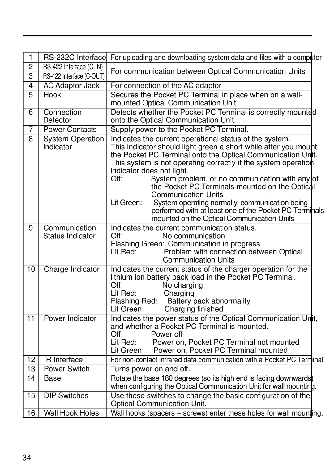
1 |
| For uploading and downloading system data and files with a computer | ||
2 | For communication between Optical Communication Units | |||
3 | ||||
|
| |||
4 | AC Adaptor Jack | For connection of the AC adaptor | ||
5 | Hook | Secures the Pocket PC Terminal in place when on a wall- | ||
|
| mounted Optical Communication Unit. | ||
6 | Connection | Detects whether the Pocket PC Terminal is correctly mounted | ||
| Detector | onto the Optical Communication Unit. | ||
7 | Power Contacts | Supply power to the Pocket PC Terminal. | ||
8 | System Operation | Indicates the current operational status of the system. | ||
| Indicator | This indicator should light green a short while after you mount | ||
|
| the Pocket PC Terminal onto the Optical Communication Unit. | ||
|
| This system is not operating correctly if the system operation | ||
|
| indicator does not light. | ||
|
| Off: | System problem, or no communication with any of | |
|
|
| the Pocket PC Terminals mounted on the Optical | |
|
|
| Communication Units | |
|
| Lit Green: | System operating normally, communication being | |
|
|
| performed with at least one of the Pocket PC Terminals | |
|
|
| mounted on the Optical Communication Units | |
9 | Communication | Indicates the current communication status. | ||
| Status Indicator | Off: | No communication | |
|
| Flashing Green: Communication in progress | ||
|
| Lit Red: | Problem with connection between Optical | |
|
|
| Communication Units | |
10 | Charge Indicator | Indicates the current status of the charger operation for the | ||
|
| lithium ion battery pack load in the Pocket PC Terminal. | ||
|
| Off: | No charging | |
|
| Lit Red: | Charging | |
|
| Flashing Red: Battery pack abnormality | ||
|
| Lit Green: | Charging finished | |
11 | Power Indicator | Indicates the power status of the Optical Communication Unit, | ||
|
| and whether a Pocket PC Terminal is mounted. | ||
|
| Off: | Power off | |
|
| Lit Red: | Power on, Pocket PC Terminal not mounted | |
|
| Lit Green: | Power on, Pocket PC Terminal mounted | |
12 | IR Interface | For | ||
13 | Power Switch | Turns power on and off. | ||
14 | Base | Rotate the base 180 degrees (so its high end is facing downwards) | ||
|
| when configuring the Optical Communication Unit for wall mounting. | ||
15 | DIP Switches | Use these switches to change the basic configuration of the | ||
|
| Optical Communication Unit. | ||
16 | Wall Hook Holes | Wall hooks (spacers + screws) enter these holes for wall mounting. | ||
34