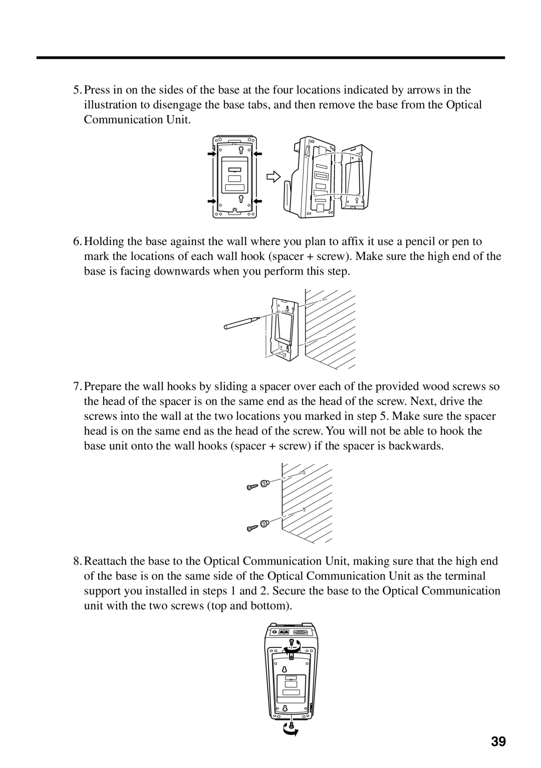
5.Press in on the sides of the base at the four locations indicated by arrows in the illustration to disengage the base tabs, and then remove the base from the Optical Communication Unit.
6.Holding the base against the wall where you plan to affix it use a pencil or pen to mark the locations of each wall hook (spacer + screw). Make sure the high end of the base is facing downwards when you perform this step.
7.Prepare the wall hooks by sliding a spacer over each of the provided wood screws so the head of the spacer is on the same end as the head of the screw. Next, drive the screws into the wall at the two locations you marked in step 5. Make sure the spacer head is on the same end as the head of the screw. You will not be able to hook the base unit onto the wall hooks (spacer + screw) if the spacer is backwards.
8.Reattach the base to the Optical Communication Unit, making sure that the high end of the base is on the same side of the Optical Communication Unit as the terminal support you installed in steps 1 and 2. Secure the base to the Optical Communication unit with the two screws (top and bottom).
39