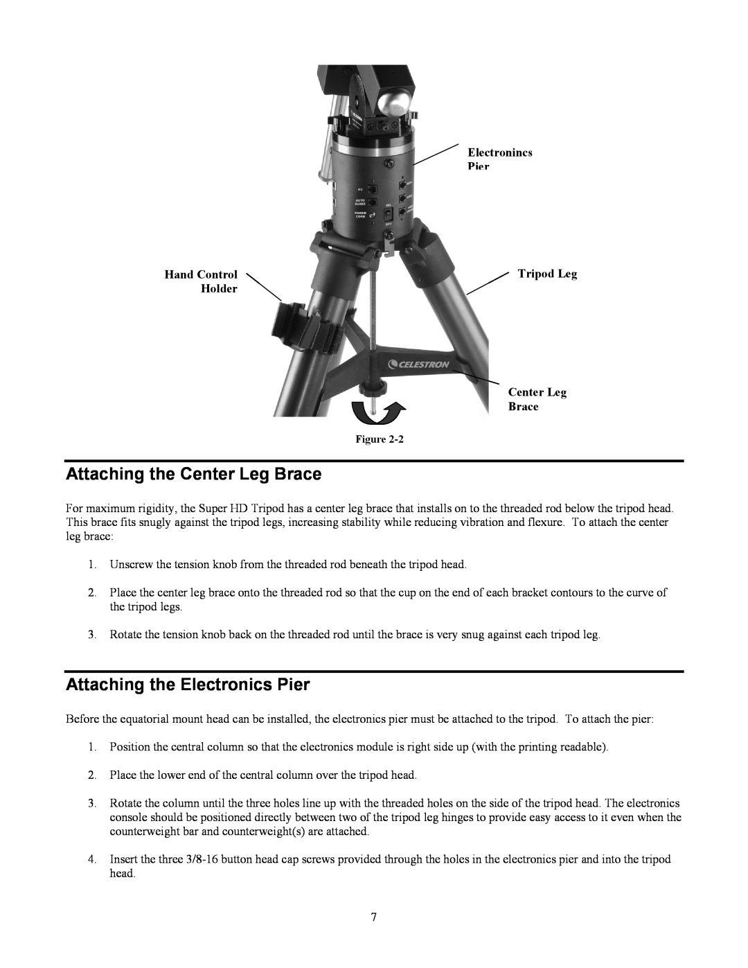
Electronincs
Pier
Hand Control | Tripod Leg |
Holder |
|
Center Leg
Brace
Figure
Attaching the Center Leg Brace
For maximum rigidity, the Super HD Tripod has a center leg brace that installs on to the threaded rod below the tripod head. This brace fits snugly against the tripod legs, increasing stability while reducing vibration and flexure. To attach the center leg brace:
1.Unscrew the tension knob from the threaded rod beneath the tripod head.
2.Place the center leg brace onto the threaded rod so that the cup on the end of each bracket contours to the curve of the tripod legs.
3.Rotate the tension knob back on the threaded rod until the brace is very snug against each tripod leg.
Attaching the Electronics Pier
Before the equatorial mount head can be installed, the electronics pier must be attached to the tripod. To attach the pier:
1.Position the central column so that the electronics module is right side up (with the printing readable).
2.Place the lower end of the central column over the tripod head.
3.Rotate the column until the three holes line up with the threaded holes on the side of the tripod head. The electronics console should be positioned directly between two of the tripod leg hinges to provide easy access to it even when the counterweight bar and counterweight(s) are attached.
4.Insert the three
7