Parallel Installation:
Minimum Clearance and Flue Centerline,
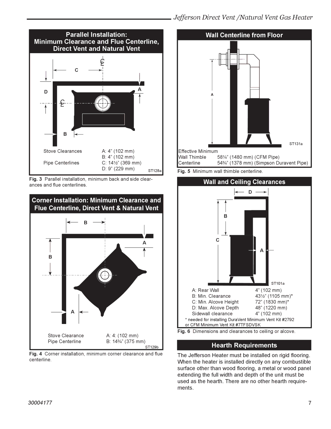
Direct Vent and Natural Vent
| C |
| L |
| C |
D | A |
|
C
L
|
| B |
|
|
|
|
|
|
|
|
|
| |
Stove Clearances | A: 4” (102 mm) |
| ||||
|
|
|
|
| B: 4” (102 mm) |
|
Pipe Centerlines | C: 14¹⁄₂” (369 mm) |
| ||||
|
|
|
|
| D: 9” (229 mm) | ST128a |
|
|
|
|
|
| |
Fig. 3 Parallel installation, minimum back and side clear- ances and flue centerlines.
Corner Installation: Minimum Clearance and Flue Centerline, Direct Vent & Natural Vent
B
A
B
|
| A |
|
|
|
|
|
|
| ||
|
|
|
|
|
|
Stove Clearance | A: 4: (102 mm) | ||||
Pipe Centerline | B: 14³⁄₄” (375 mm) | ||||
|
|
|
|
| ST129b |
Fig. 4 Corner installation, minimum corner clearance and flue centerline.
Jefferson Direct Vent /Natural Vent Gas Heater
Wall Centerline from Floor
A
|
|
| ST131a |
|
|
| |
|
|
|
|
Effective Minimum | |||
Wall Thimble |
| 58¹⁄₄” (1480 mm) (CFM Pipe) | |
Centerline |
| 54³⁄₄” (1378 mm) (Simpson Duravent Pipe) | |
Fig. 5 Minimum wall thimble centerline.
Wall and Ceiling Clearances
D
B
C
![]() A
A ![]()
| ST101a |
A: Rear Wall | 4” (102 mm) |
B: Min. Clearance | 43¹⁄₂” (1105 mm)* |
C: Min. Alcove Height | 72” (1830 mm)* |
D: Max. Alcove Depth | 48” (1220 mm) |
Sidewall clearance | 4” (102 mm) |
*needed for installing DuraVent Minimum Vent Kit #2792 or CFM Minimum Vent Kit #7TFSDVSK
Fig. 6 Dimensions and clearances to ceiling or alcove.
Hearth Requirements
The Jefferson Heater must be installed on rigid flooring. When the heater is installed directly on any combustible surface other than wood flooring, a metal or wood panel extending the full width and depth of the unit must be used as the hearth. There are no other hearth require- ments.
30004177 | 7 |