Jefferson Direct Vent/Natural Vent Gas Heater
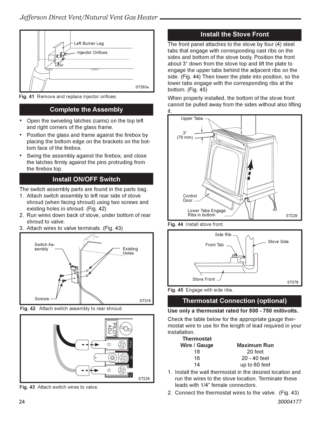
Left Burner Leg |
Injector Orifices |
90° |
ST353a
Fig. 41 Remove and replace injector orifices.
Complete the Assembly
•Open the swiveling latches (cams) on the top left and right corners of the glass frame.
•Position the glass and frame against the firebox by placing the bottom edge on the brackets on the bot- tom face of the firebox.
•Swing the assembly against the firebox, and close the latches firmly against the pins protruding from the firebox top.
Install ON/OFF Switch
The switch assembly parts are found in the parts bag.
1.Attach switch assembly to left rear side of stove shroud (when facing shroud) using two screws and existing holes in shroud. (Fig. 42)
2.Run wires down back of stove, under bottom of rear shroud to valve.
3.Attach wires to valve terminals. (Fig. 43)
Install the Stove Front
The front panel attaches to the stove by four (4) steel tabs that engage with corresponding cast ribs on the sides and bottom of the stove body. Position the front about 3” down from the stove top and lift the plate to engage the upper tabs behind the adjacent ribs on the side. (Fig. 44) Then lower the plate into position, so the lower tabs engage with the corresponding ribs at the bottom. (Fig. 45)
When properly installed, the bottom of the stove front cannot be pulled away from the sides without also lifting it.
Upper Tabs
3” ![]()
![]() (76 mm)
(76 mm) ![]()
![]()
![]()
Control
Door
Lower Tabs Engage |
|
Ribs in bottom | ST229 |
Fig. 44 Install stove front.
Side Rib
Switch As-
semblyExisting Holes
Front Tab
Stove Side
Screws | ST315 |
|
Fig. 42 Attach switch assembly to rear shroud.
PILOT |
|
ADJ |
|
TPTH |
|
TP |
|
TH | ST228 |
|
Fig. 43 Attach switch wires to valve.
Stove Front ![]()
ST279
Fig. 45 Engage with side ribs.
Thermostat Connection (optional)
Use only a thermostat rated for 500 - 750 millivolts.
Check the table below for the appropriate gauge ther- mostat wire to use for the length of lead required in your installation.
Thermostat |
|
Wire / Gauge | Maximum Run |
18 | 20 feet |
16 | 20 - 40 feet |
14 | up to 60 feet |
1.Install the wall thermostat in the desired location and run the wires to the stove location. Terminate these leads with 1/4” female connectors.
2.Connect the thermostat wires to the valve. (Fig. 43)
2424 | 30004177 |