Installation Instructions | CM2 |
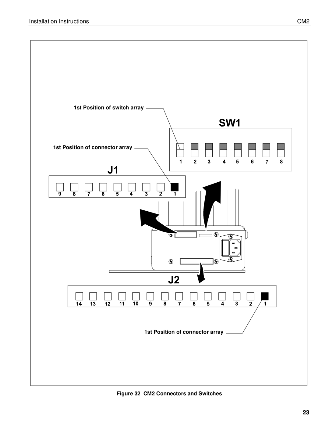
1st Position of switch array
1st Position of connector array
1st Position of connector array
Figure 32 CM2 Connectors and Switches
23
Installation Instructions | CM2 |
1st Position of switch array
1st Position of connector array
1st Position of connector array
23