Chapter 1 Product Overview
Power Subsystems
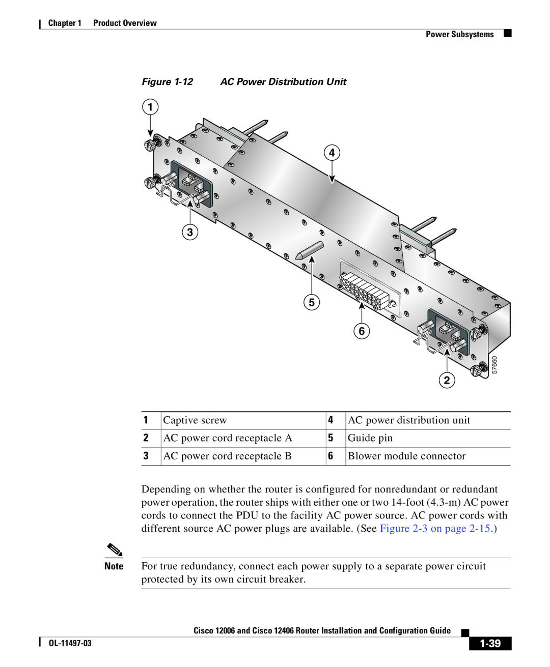
Figure 1-12 AC Power Distribution Unit
1
4
3
5
|
|
| 6 |
|
|
| 57650 |
|
|
| 2 |
1 | Captive screw | 4 | AC power distribution unit |
2 | AC power cord receptacle A | 5 | Guide pin |
3 | AC power cord receptacle B | 6 | Blower module connector |
Depending on whether the router is configured for nonredundant or redundant power operation, the router ships with either one or two
Note For true redundancy, connect each power supply to a separate power circuit protected by its own circuit breaker.
|
| Cisco 12006 and Cisco 12406 Router Installation and Configuration Guide |
|
|
|
|
| ||
|
|
| ||
|
|
|