Chapter 1 Product Overview
Power Subsystems
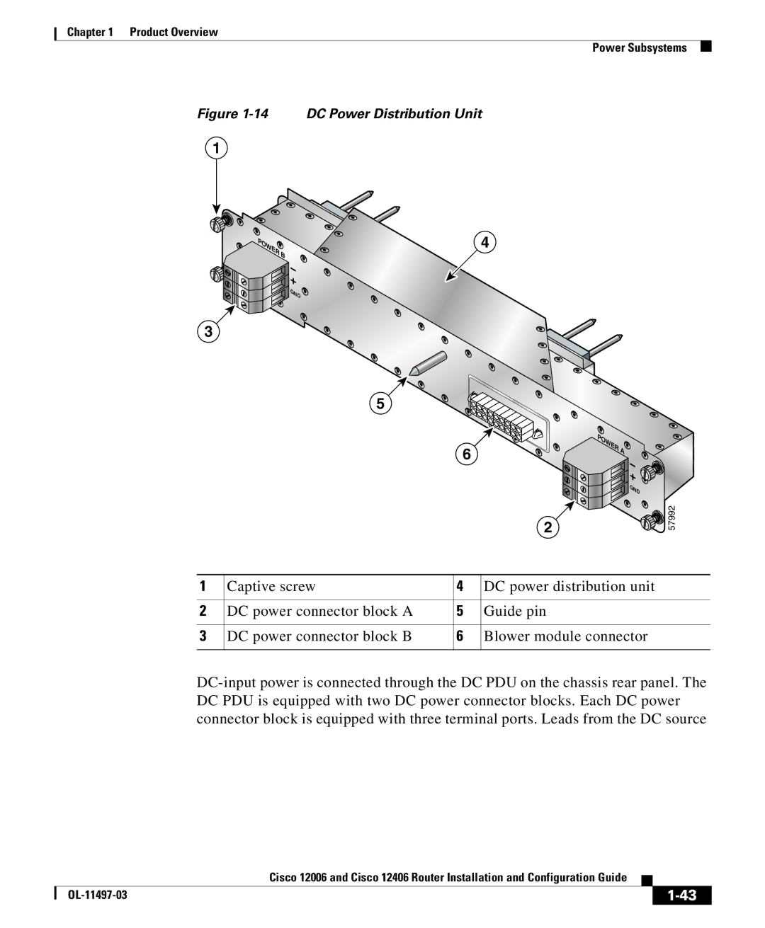
Figure 1-14 DC Power Distribution Unit
1
![]() POWER B
POWER B ![]()
![]()
![]()
![]()
![]()
![]()
![]() +
+
GND ![]()
3
4
5
6
2
POWER A![]()
![]()
![]() +
+ ![]()
![]() GND
GND
57992
1 | Captive screw | 4 | DC power distribution unit |
|
|
|
|
2 | DC power connector block A | 5 | Guide pin |
|
|
|
|
3 | DC power connector block B | 6 | Blower module connector |
|
|
|
|
|
| Cisco 12006 and Cisco 12406 Router Installation and Configuration Guide |
|
|
|
|
| ||
|
|
| ||
|
|
|