Chapter 1 Product Overview
Blower Module
•OK—Left LED; Green. When on, this LED indicates that the blower module is operating normally. This LED should come on as soon as the blower module is installed and receives power from the backplane connector.
•FAIL—Right LED; Red. The red LED should remain off during normal operation. If the red LED is on, the system has detected a fan failure or other fault in the blower module. Replace the existing blower module with a spare.
Air Filters
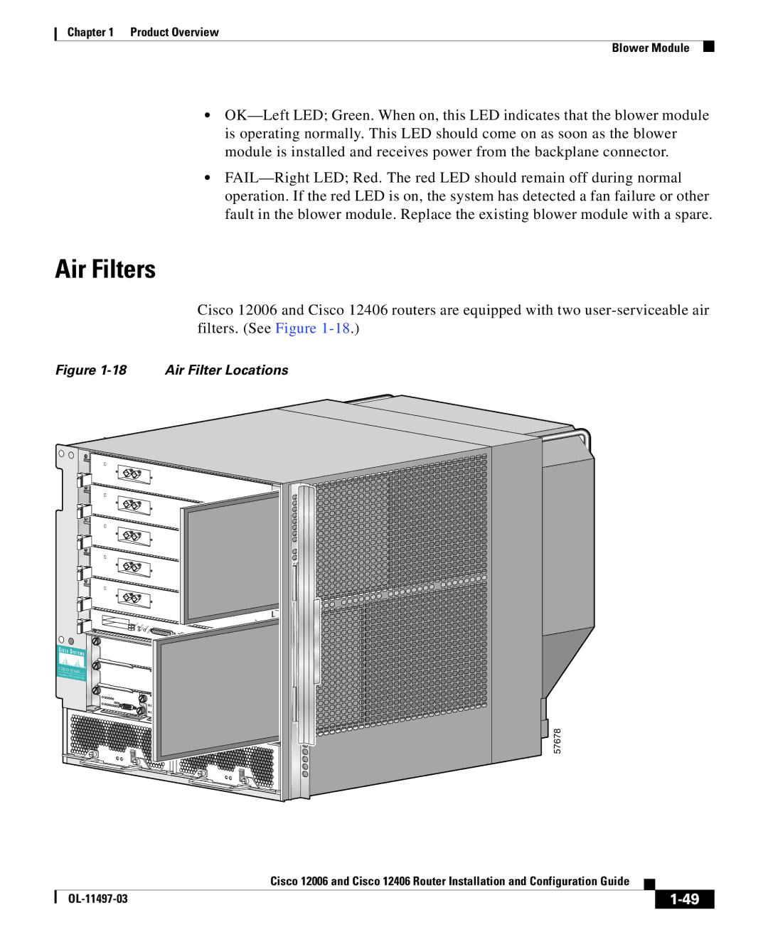
Cisco 12006 and Cisco 12406 routers are equipped with two user-serviceable air filters. (See Figure 1-18.)
Figure 1-18 Air Filter Locations
AUX
CISCO 12000 SERIES
GIGABIT SWITCH ROUTER
57678
| | Cisco 12006 and Cisco 12406 Router Installation and Configuration Guide | | |
| | |
| OL-11497-03 | | | 1-49 |
| | |