Chapter 1 Product Overview
Power Subsystems
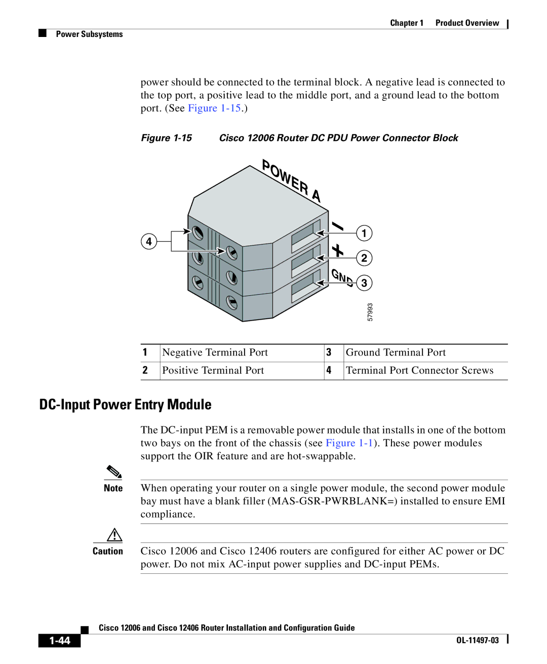
power should be connected to the terminal block. A negative lead is connected to the top port, a positive lead to the middle port, and a ground lead to the bottom port. (See Figure
Figure 1-15 Cisco 12006 Router DC PDU Power Connector Block
POWER A
4
![]()

![]()
![]()
![]() +
+ ![]()
![]()
![]() GND
GND
1
2
3
|
|
| 57993 |
1 | Negative Terminal Port | 3 | Ground Terminal Port |
2 | Positive Terminal Port | 4 | Terminal Port Connector Screws |
DC-Input Power Entry Module
The
Note When operating your router on a single power module, the second power module bay must have a blank filler
Caution Cisco 12006 and Cisco 12406 routers are configured for either AC power or DC power. Do not mix
| Cisco 12006 and Cisco 12406 Router Installation and Configuration Guide |