Chapter 1 Product Overview
Power Subsystems
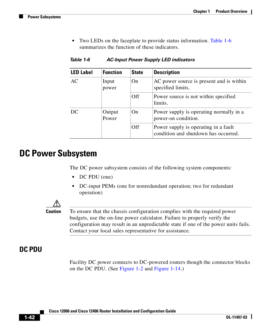
•Two LEDs on the faceplate to provide status information. Table
Table | |||
|
|
|
|
LED Label | Function | State | Description |
|
|
|
|
AC | Input | On | AC power source is present and is within |
| power |
| specified limits. |
|
|
|
|
|
| Off | Power source is not within specified |
|
|
| limits. |
|
|
|
|
DC | Output | On | Power supply is operating normally in a |
| Power |
| |
|
|
|
|
|
| Off | Power supply is operating in a fault |
|
|
| condition and shutdown has occurred. |
|
|
|
|
DC Power Subsystem
The DC power subsystem consists of the following system components:
•DC PDU (one)
•
Caution To ensure that the chassis configuration complies with the required power budgets, use the
DC PDU
Facility DC power connects to
| Cisco 12006 and Cisco 12406 Router Installation and Configuration Guide |
