Chapter 1 Product Overview
Blower Module
If the air temperature inside the RP and line card cage rises, the system environmental monitor shuts down all internal power to prevent equipment damage from excessive heat.
If the system detects that one of three fans within a blower module has failed, it displays a warning message on the console screen. If multiple fans fail, the system shuts down to prevent equipment damage.
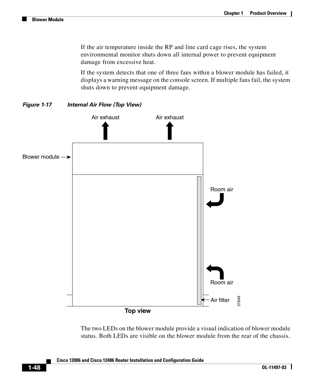
Figure 1-17 Internal Air Flow (Top View)
Air exhaust | Air exhaust |
Blower module ![]()
Room air
Room air
![]() Air filter
Air filter
Top view
57649
The two LEDs on the blower module provide a visual indication of blower module status. Both LEDs are visible on the blower module from the rear of the chassis.
| Cisco 12006 and Cisco 12406 Router Installation and Configuration Guide |