Deployment and Design Requirements
Step 21 At the new floor’s image window (Monitor > Maps > [CampusName] > [BuildingName] > [FloorName]), go to the
Step 22 All access points that are connected to controllers, which WCS is configured to manage and which have yet to be added to another floor map, are displayed. Select which access points need to be placed on the specific floor map by checking the boxes to the left of the access point entries. Check the box to the left of the Name column to select all access points. Click OK.
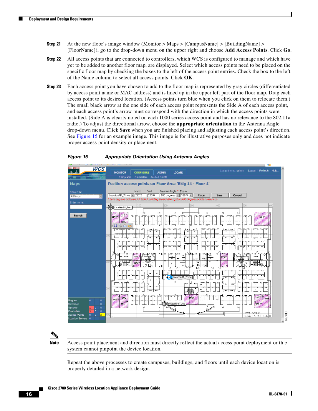
Step 23 Each access point you have chosen to add to the floor map is represented by gray circles (differentiated by access point name or MAC address) and is lined up in the upper left part of the floor map. Drag each access point to its desired location. (Access points turn blue when you click on them to relocate them.) The small black arrow at the one side of each access point represents the Side A of each access point, and each access point’s arrow must correspond with the direction in which the access points were installed. (Side A is clearly noted on each 1000 series access point and has no relevance to the 802.11a radio.) To adjust the directional arrow, choose the appropriate orientation in the Antenna Angle
Figure 15 Appropriate Orientation Using Antenna Angles
Note Access point placement and direction must directly reflect the actual access point deployment or th e system cannot pinpoint the device location.
Repeat the above processes to create campuses, buildings, and floors until each device location is properly detailed in a network design.
Cisco 2700 Series Wireless Location Appliance Deployment Guide
16 |
| |
|