Deployment and Design Requirements
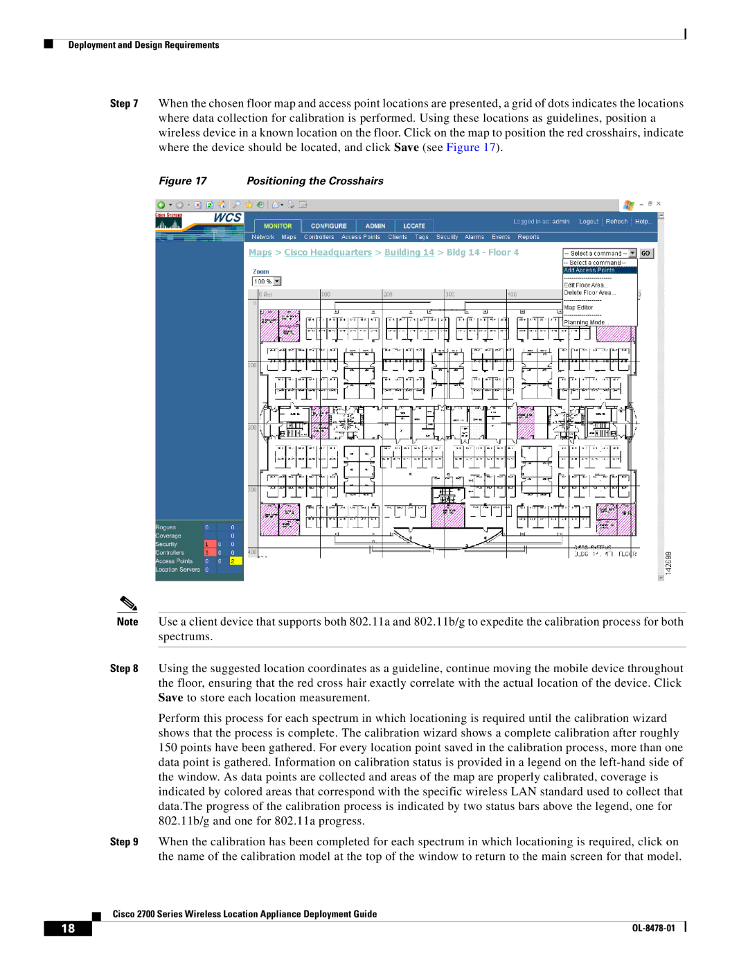
Step 7 When the chosen floor map and access point locations are presented, a grid of dots indicates the locations where data collection for calibration is performed. Using these locations as guidelines, position a wireless device in a known location on the floor. Click on the map to position the red crosshairs, indicate where the device should be located, and click Save (see Figure 17).
Figure 17 | Positioning the Crosshairs |
Note Use a client device that supports both 802.11a and 802.11b/g to expedite the calibration process for both spectrums.
Step 8 Using the suggested location coordinates as a guideline, continue moving the mobile device throughout the floor, ensuring that the red cross hair exactly correlate with the actual location of the device. Click Save to store each location measurement.
Perform this process for each spectrum in which locationing is required until the calibration wizard shows that the process is complete. The calibration wizard shows a complete calibration after roughly 150 points have been gathered. For every location point saved in the calibration process, more than one data point is gathered. Information on calibration status is provided in a legend on the
Step 9 When the calibration has been completed for each spectrum in which locationing is required, click on the name of the calibration model at the top of the window to return to the main screen for that model.
Cisco 2700 Series Wireless Location Appliance Deployment Guide
18 |
| |
|