Deployment and Design Requirements
the buildings that comprise that campus, and the floors of each building constitute a single network design. The location appliance is set to poll the controllers in that network, as well as be configured to synchronize with that specific network design, in order to track devices in that environment. The concept and steps to perform synchronization between WCS and the location appliance is explained in “Importing the Location Appliance into WCS, page 20.”
Designing a Network
Follow these steps to design a network.
Step 1 Open WCS’s web interface and log in.
Note To create or edit a network design, you must log into WCS and have SuperUser, Admin, or ConfigManager access privileges.
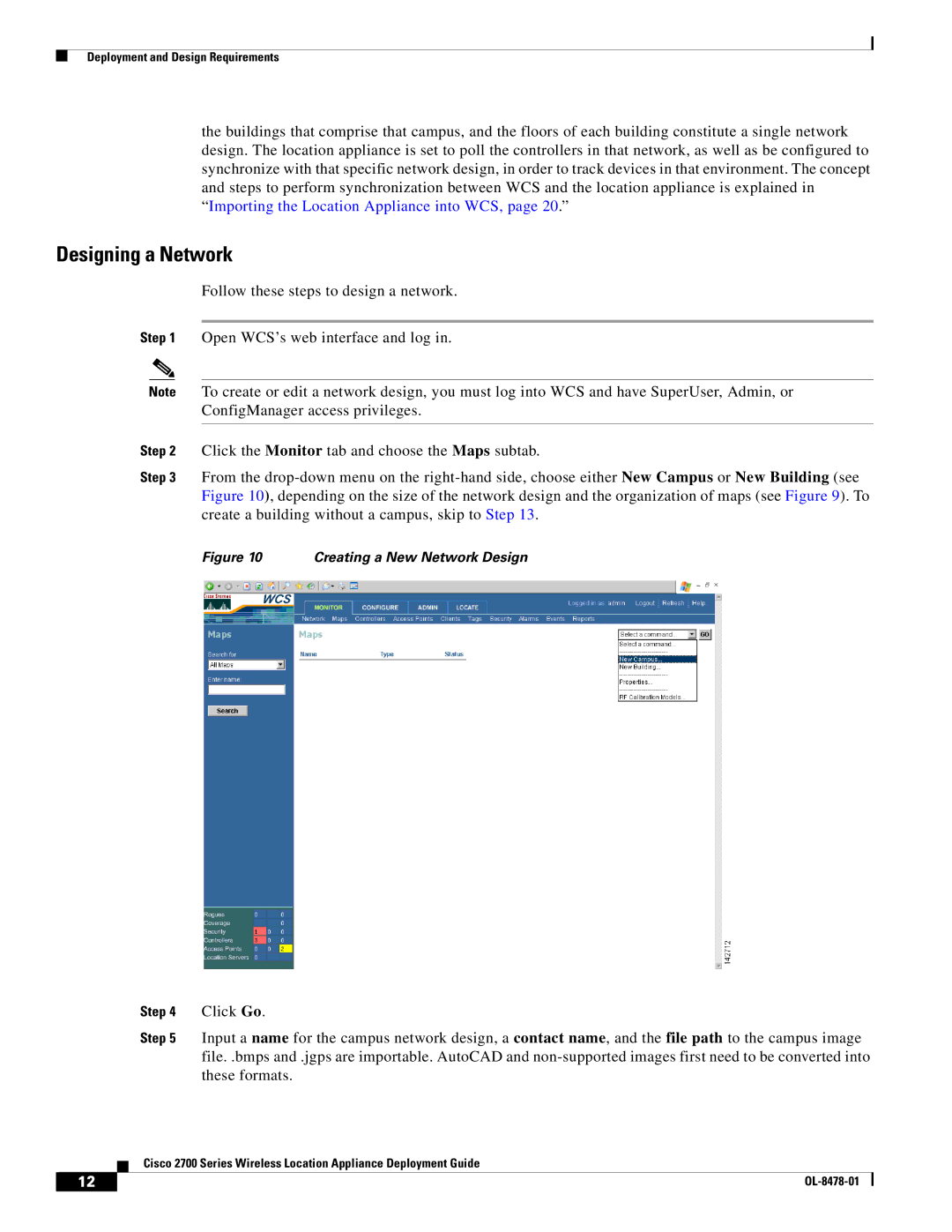
Step 2 Click the Monitor tab and choose the Maps subtab.
Step 3 From the
Figure 10 Creating a New Network Design
Step 4 Click Go.
Step 5 Input a name for the campus network design, a contact name, and the file path to the campus image file. .bmps and .jgps are importable. AutoCAD and
Cisco 2700 Series Wireless Location Appliance Deployment Guide
12 |
| |
|