Chapter 7 Maintaining the Cisco Catalyst 5500 Multiswitch Router
Checking Equipment Status
10/100 Mbps Fast Ethernet Switching Module (10/100BaseTX 12 Port) LEDs
The faceplate of each 10/100 Mbps Fast Ethernet Switching Module (Prod #
Table
LED | Description |
STATUS | The switch performs a series of |
| If it passes all the tests, the LED is green. |
| If it fails a test other than an individual port test fails, the LED is red. |
| During system boot or if the module is disabled, the LED is orange. |
| During |
| If the module is disabled, the LED is orange. |
|
|
100 Mbps | If the port is operating at 100 Mbps, the LED is green. |
| If the port is operating at 10 Mbps, the LED is off. |
LINK (bottom LED)
If the port is operational (a signal is detected), the LED is green.
If the link has been disabled by software, the LED is orange.
If the link is bad and has been disabled due to a hardware failure, the LED flashes orange.
If no signal is detected, the LED is off.
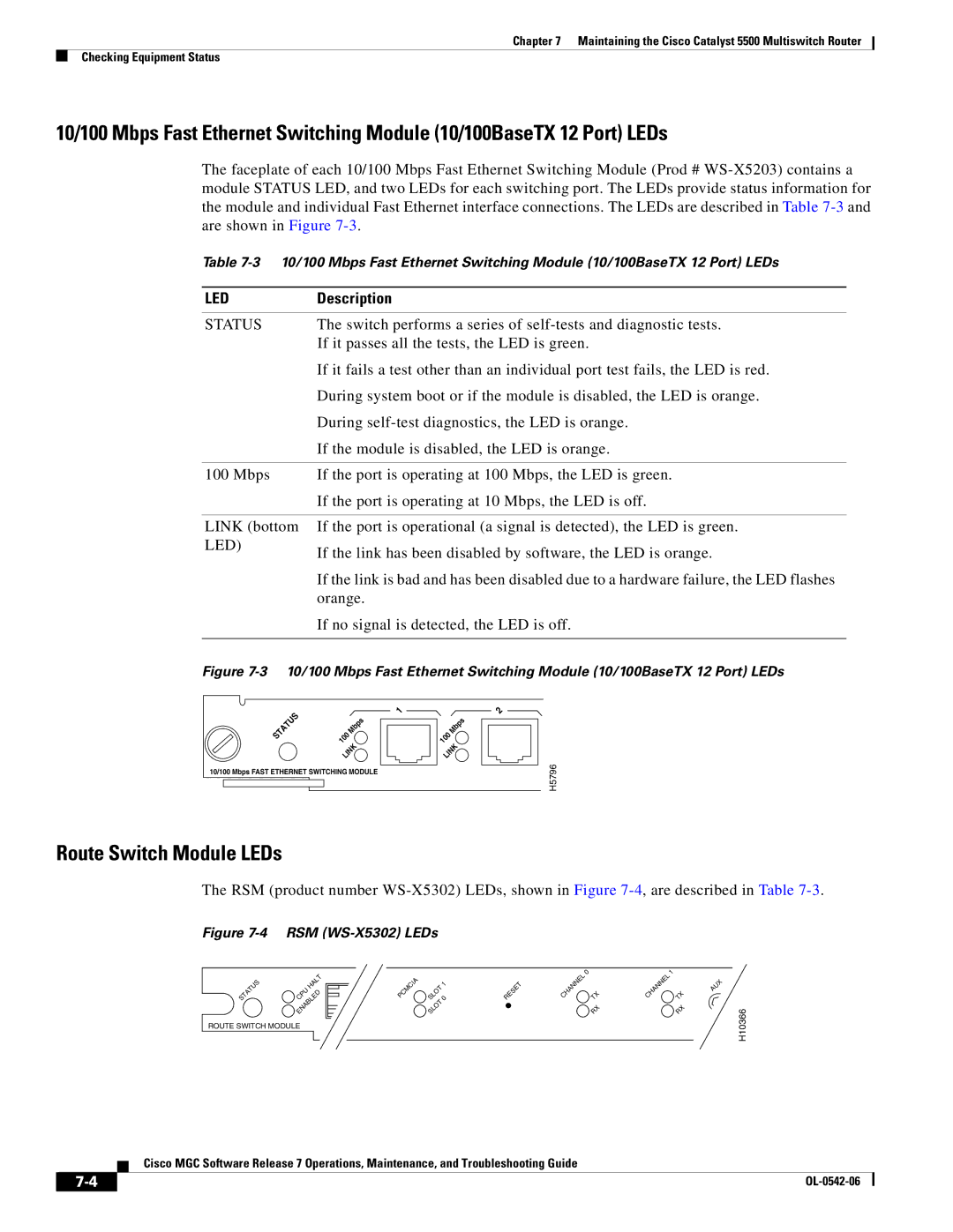
Figure 7-3 10/100 Mbps Fast Ethernet Switching Module (10/100BaseTX 12 Port) LEDs
STATUS | 100 | Mbps |
|
| |
| LINK | |
10/100 Mbps FAST ETHERNET SWITCHING MODULE
1
2
100 | Mbps |
| |
LINK | |
H5796
Route Switch Module LEDs
The RSM (product number
Figure 7-4 RSM (WS-X5302) LEDs
STATUS | HALT |
CPU | |
| ENABLED |
ROUTE SWITCH MODULE
PCMCIA | SLOT 0 | RESET | CHANNEL | 0 | TX | CHANNEL | 1 |
| TX | ||||||
| 1 |
|
|
|
|
| AUX |
|
|
|
|
|
|
| |
| SLOT |
|
|
| RX |
| RX |
H10366
Cisco MGC Software Release 7 Operations, Maintenance, and Troubleshooting Guide
| ||
|