Chapter 7 Maintaining the Cisco Catalyst 5500 Multiswitch Router
Checking Equipment Status
Table
LED | State | Description |
|
|
|
SLOT 1 | On | Supervisor Engine III only: The Flash PC Card SLOT 1 and SLOT 0 |
and |
| LEDs light when their respective slot 1 and slot 0 Flash PC Card devices |
SLOT 0 |
| are accessed. |
|
|
|
100 Mbps | Green | The port is operating at 100 Mbps. |
|
|
|
1000 Mbps | Green | The port is operating at 1000 Mbps. |
|
|
|
LINK | Green | The port is operational. |
| Orange | The link has been disabled by software. |
| Flashing | The link is bad and has been disabled due to a hardware failure. |
| orange |
|
| Off | No signal is detected. |
|
|
|
Ethernet Switching Module (10BaseT 24 Port) LEDs
Each switching module (Prod #
The LEDs on the faceplate of the Ethernet switching module (10BaseT 24 Port) are described in Table
Table
LED | Description |
|
|
STATUS | The switch performs a series of |
| If it passes all the tests, the status LED is green. |
| If it fails any test, the status LED is red (or orange for a minor fault or if manually |
| disabled). |
|
|
Link | If the port is operational (a signal is detected), the LED is green. |
| If the link has been disabled by software, the LED is orange. |
| If the link is bad and has been disabled due to a hardware failure, the LED flashes |
| orange. |
| If no signal is detected, the LED is off. |
|
|
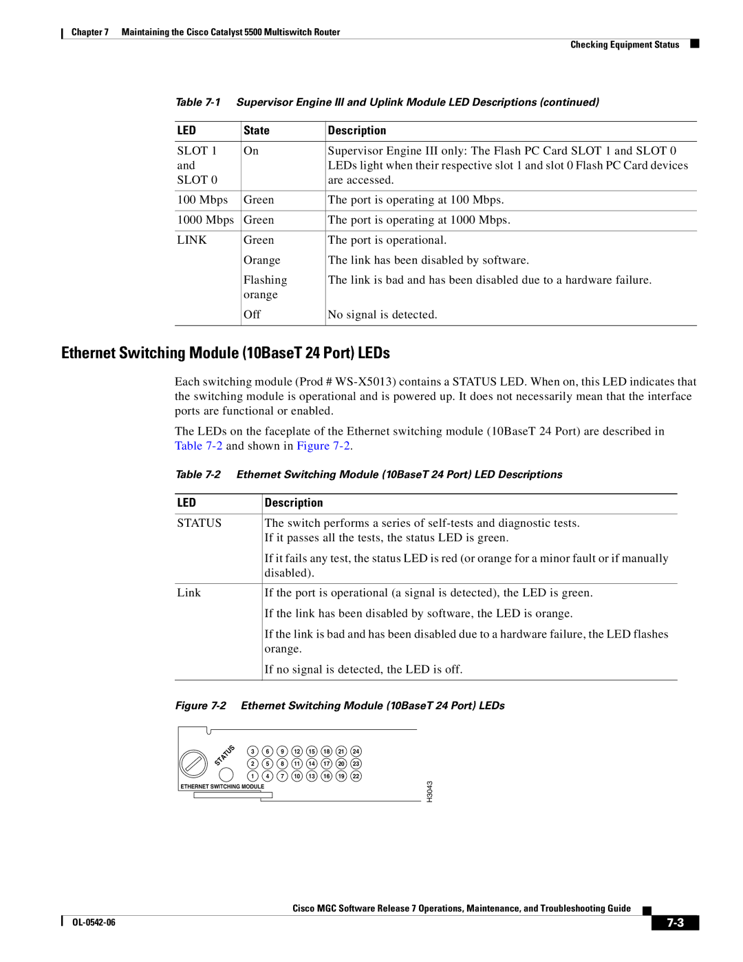
Figure 7-2 Ethernet Switching Module (10BaseT 24 Port) LEDs
3 | 6 | 9 | 12 | 15 | 18 | 21 | 24 |
2 | 5 | 8 | 11 | 14 | 17 | 20 | 23 |
1 | 4 | 7 | 10 | 13 | 16 | 19 | 22 |
ETHERNET SWITCHING MODULE
H3043
Cisco MGC Software Release 7 Operations, Maintenance, and Troubleshooting Guide
|
| ||
|
|