Chapter 7 Maintaining the Cisco Catalyst 5500 Multiswitch Router
Replacing Hardware Components
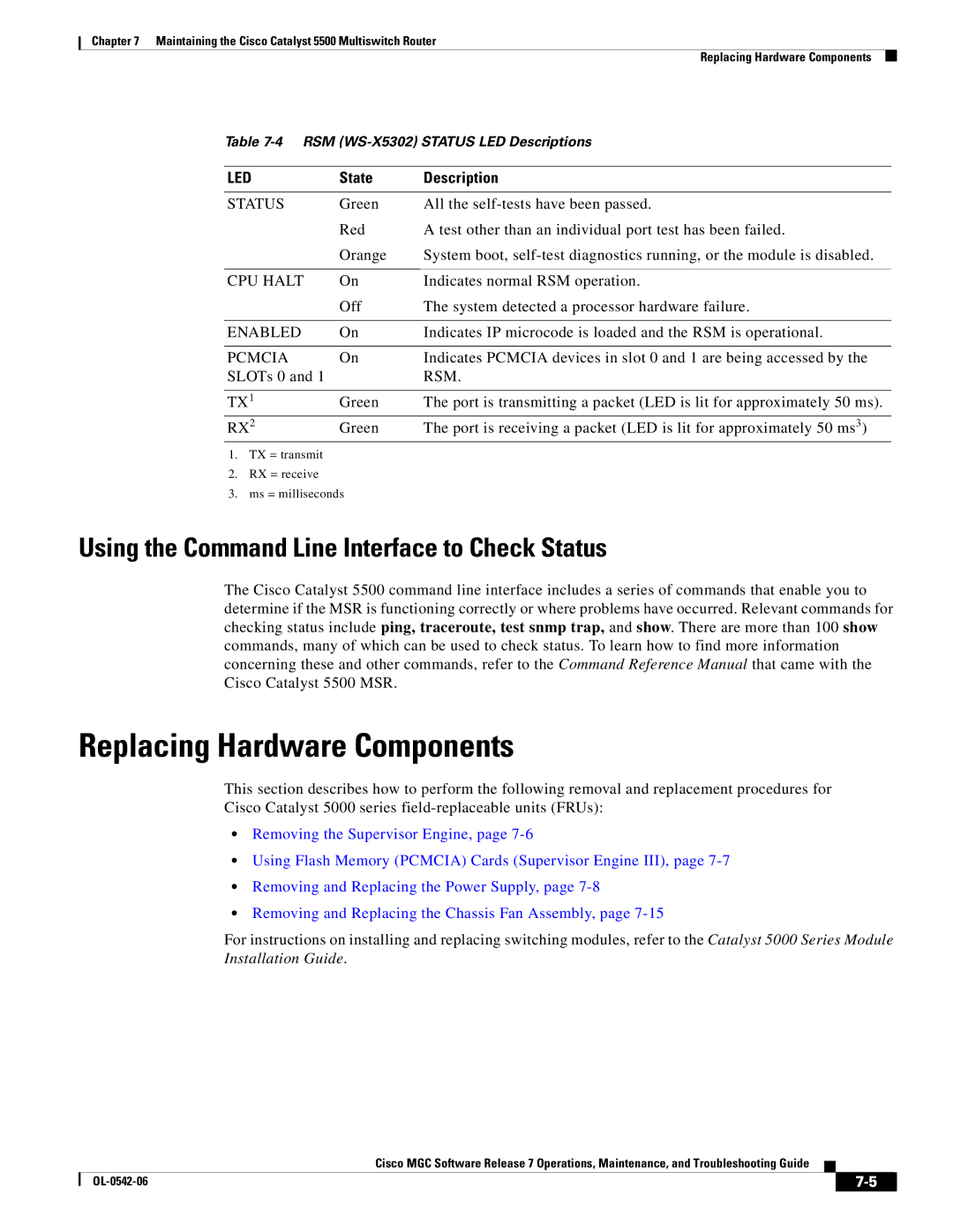
Table
LED | State | Description |
STATUS | Green | All the |
| Red | A test other than an individual port test has been failed. |
| Orange | System boot, |
|
|
|
CPU HALT | On | Indicates normal RSM operation. |
| Off | The system detected a processor hardware failure. |
|
|
|
ENABLED | On | Indicates IP microcode is loaded and the RSM is operational. |
|
|
|
PCMCIA | On | Indicates PCMCIA devices in slot 0 and 1 are being accessed by the |
SLOTs 0 and 1 |
| RSM. |
|
|
|
TX1 | Green | The port is transmitting a packet (LED is lit for approximately 50 ms). |
RX2 | Green | The port is receiving a packet (LED is lit for approximately 50 ms3) |
1.TX = transmit
2.RX = receive
3.ms = milliseconds
Using the Command Line Interface to Check Status
The Cisco Catalyst 5500 command line interface includes a series of commands that enable you to determine if the MSR is functioning correctly or where problems have occurred. Relevant commands for checking status include ping, traceroute, test snmp trap, and show. There are more than 100 show commands, many of which can be used to check status. To learn how to find more information concerning these and other commands, refer to the Command Reference Manual that came with the Cisco Catalyst 5500 MSR.
Replacing Hardware Components
This section describes how to perform the following removal and replacement procedures for
Cisco Catalyst 5000 series
•Removing the Supervisor Engine, page
•Using Flash Memory (PCMCIA) Cards (Supervisor Engine III), page
•Removing and Replacing the Power Supply, page
•Removing and Replacing the Chassis Fan Assembly, page
For instructions on installing and replacing switching modules, refer to the Catalyst 5000 Series Module Installation Guide.
Cisco MGC Software Release 7 Operations, Maintenance, and Troubleshooting Guide
|
| ||
|
|