Chapter 7 Maintaining the Cisco Catalyst 5500 Multiswitch Router
Replacing Hardware Components
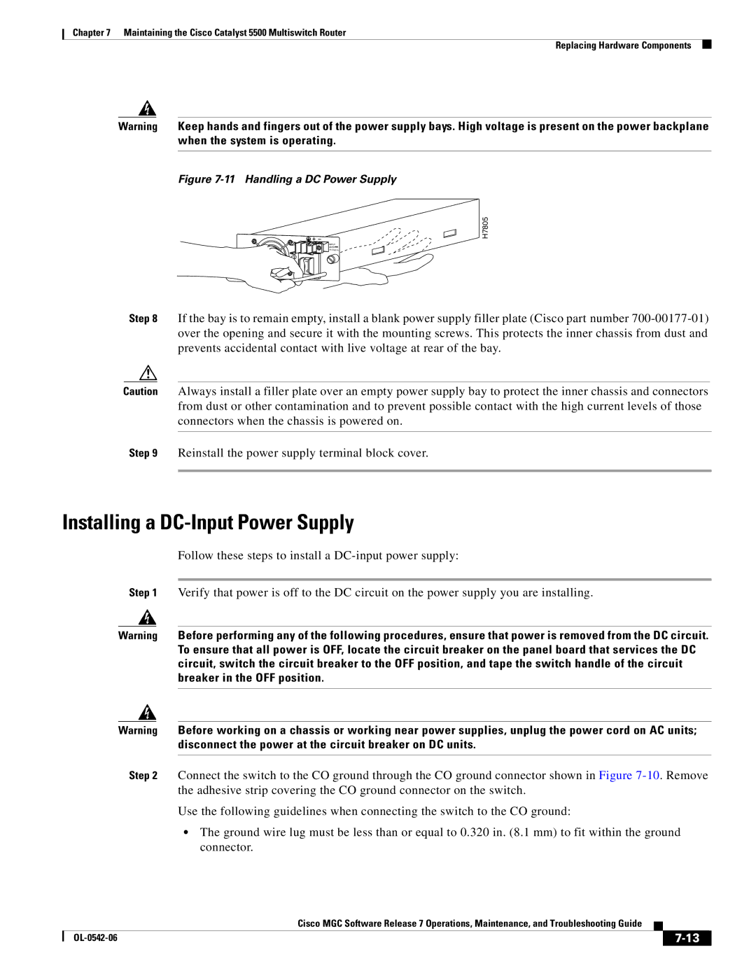
Warning Keep hands and fingers out of the power supply bays. High voltage is present on the power backplane when the system is operating.
Figure 7-11 Handling a DC Power Supply
H7805
![]()
![]()
![]() INPUT 48/60 14.0/8.0 A
INPUT 48/60 14.0/8.0 A
Step 8 If the bay is to remain empty, install a blank power supply filler plate (Cisco part number
Caution Always install a filler plate over an empty power supply bay to protect the inner chassis and connectors from dust or other contamination and to prevent possible contact with the high current levels of those connectors when the chassis is powered on.
Step 9 Reinstall the power supply terminal block cover.
Installing a DC-Input Power Supply
Follow these steps to install a
Step 1 Verify that power is off to the DC circuit on the power supply you are installing.
Warning Before performing any of the following procedures, ensure that power is removed from the DC circuit. To ensure that all power is OFF, locate the circuit breaker on the panel board that services the DC circuit, switch the circuit breaker to the OFF position, and tape the switch handle of the circuit breaker in the OFF position.
Warning Before working on a chassis or working near power supplies, unplug the power cord on AC units; disconnect the power at the circuit breaker on DC units.
Step 2 Connect the switch to the CO ground through the CO ground connector shown in Figure
Use the following guidelines when connecting the switch to the CO ground:
•The ground wire lug must be less than or equal to 0.320 in. (8.1 mm) to fit within the ground connector.
Cisco MGC Software Release 7 Operations, Maintenance, and Troubleshooting Guide
|
| ||
|
|